Steel fiber feeding and dispersing device and dispersing method

A technology of dispersing device and steel fiber, applied in the direction of selling raw material supply device, pretreatment control, etc., can solve the problems of uneven dispersion and low dispersion efficiency of steel fiber, and achieve the effect of uniform dispersion, high efficiency and uniform feeding.

Active Publication Date: 2018-11-23
成都东蓝星新材料有限公司
View PDF5 Cites 7 Cited by
  • Summary
  • Abstract
  • Description
  • Claims
  • Application Information

AI Technical Summary

Problems solved by technology

[0003] The purpose of the present invention is to overcome the deficiencies of the prior art, provide a steel fiber feeding dispersion device and dispersion method, and solve the problems of uneven dispersion and low dispersion efficiency of steel fibers

Method used


Image

  • Steel fiber feeding and dispersing device and dispersing method

Examples


Embodiment 1

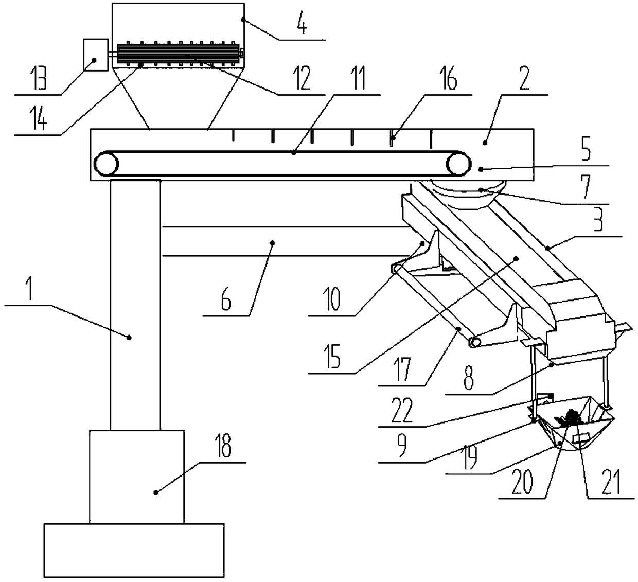
[0026] Such as figure 1 As shown, a kind of steel fiber feeding dispersing device of the present invention comprises dispersing support column 1, steel fiber conveying dispersing arm 2 and steel fiber rotating rocker 3, and described steel fiber conveying dispersing arm 2 is provided with feeding conveyer belt 11, so The bottom surface of one end of the steel fiber conveying dispersing arm 2 is arranged on the upper end of the dispersing support column 1, a dispersing hopper 4 is arranged on the end, and the bottom surface of the other end of the steel fiber conveying dispersing arm 2 is provided with a discharge port 5;

[0027] The dispersing hopper 4 is provided with a lowering cage 12, and the lowering cage 12 is driven to rotate by the lowering cage motor 13 arranged outside the dispersing hopper 4, and scraping target teeth are randomly arranged on the ribs of the lowering cage 12. 14. Continuously rotate the blanking cage 12, and place piles of steel fibers on the upper...

Embodiment 2

[0037] Such as figure 1 Shown, a kind of steel fiber feeding dispersion method of the present invention comprises steps:

[0038] Step 1. A conveying conveyor belt 11 is provided in the steel fiber conveying and dispersing arm 2. The bottom surface of one end of the steel fiber conveying and dispersing arm 2 is arranged on the upper end of the dispersing support column 1. A dispersing hopper 4 is arranged on the end, and the steel fiber conveying and dispersing The bottom surface of the other end of the arm 2 is provided with a discharge port 5;

[0039] Step 2, a blanking cage 12 is provided in the dispersion hopper 4, and the blanking cage 12 is driven to rotate by a blanking cage motor 13 arranged outside the dispersion hopper 4, and a scraper is arranged on the ribs of the blanking cage 12 in disorder The target teeth 14 are constantly rotating in the lower material cage 12, and the piles of steel fibers placed on the upper part of the lower material cage 12 are continuou...


PUM


Abstract

The invention discloses a steel fiber feeding and dispersing device and a dispersing method. A conveyor belt is arranged in a steel fiber conveying and dispersing arm, and the bottom surface of one end of the steel fiber conveying and dispersing arm is arranged at the upper end of a dispersing support column; a dispersing hopper is arranged on the end head of the steel fiber conveying and dispersing arm, and a discharge port is formed in the bottom surface of the other end of the steel fiber conveying and dispersing arm; a blanking cage is arranged in the dispersing hopper, and the blanking cage is driven by a blanking cage motor arranged outside the dispersing hopper to rotate; scrapping rake teeth are arranged on cage ribs of the blanking cage in disorder, the blanking cage continuouslyrotates, the steel fibers stacked at the upper part of the blanking cage are continuously racked off by the scraping rake teeth, and the dropped steel fibers are dispersed on the conveyor belt throughthe blanking cage; a rotary rocker arm support rack is arranged the dispersing support column corresponding to the lower part of the steel fiber conveying and dispersing arm, and the bottom surface of one end of a steel fiber rotary rocker arm is arranged at the outer end part of the rotary rocker arm support rack; a steel fiber receiving hopper is arranged on the end head of the steel fiber rotary rocker arm.

Description

technical field [0001] The invention relates to the technical field of construction equipment for construction engineering, in particular to a steel fiber feeding and dispersing device and a dispersing method. Background technique [0002] In concrete engineering, in order to enhance the crack resistance and wear resistance of concrete or mortar, a certain proportion of steel fibers can be added to form steel fiber concrete. The key to the production of steel fiber reinforced concrete is to disperse the steel fibers evenly in the concrete. If boxes of steel fibers are put directly into the mixer, the mixed mixture often contains fiber balls that cannot be dispersed. In order to improve the uniform dispersion effect of the steel fiber, the steel fiber should be dispersed by the disperser before entering the mixer. At present, the commonly used steel fiber dispersers include vibration type, shaking type, screen cylinder rotary type and centrifugal type. Most of the existing...

Claims


Application Information

Patent Timeline
Patent Type & Authority Applications(China)
IPC IPC(8): B28C7/06B28C7/08
CPCB28C7/0007B28C7/06B28C7/08
Inventor 陈剑梁勇刘自力
Owner 成都东蓝星新材料有限公司
Why Eureka
Try Eureka