
Micro-grid three-phase thyristor fast switch and control method

A fast switching and thyristor technology, applied in electrical components, circuit devices, AC network circuits, etc., can solve the problem that the static transfer switch is not forced to turn off, it is difficult to meet the requirements of completing on-grid switching within 10ms of the microgrid, and it is difficult to apply microgrids. Power grid system and other problems, to achieve the effect of solving the capacitor discharge to the micro grid

Active Publication Date: 2018-11-23
NANJING GUODIAN NANZI POWER GRID AUTOMATION CO LTD
View PDF2 Cites 4 Cited by
  • Summary
  • Abstract
  • Description
  • Claims
  • Application Information

AI Technical Summary

Problems solved by technology

[0003] Traditional fast switches mostly use mechanical contact structures, which are difficult to meet the requirements of microgrids to complete and off-grid switching within 10ms, and the static transfer switches commonly used on UPS also use thyristor power devices, but since the thyristor itself does not have reverse shutdown function, and the static transfer switch has no functional requirements for forced shutdown
The fast switch on the DC high-voltage system generally adopts the GTO device with the shutdown function, which is expensive and difficult to apply to the micro-grid system. There are also some thyristor back-voltage circuits in the low-voltage DC system, but the reliability is low, and because the AC system commutation problem, it is difficult to apply in microgrid engineering

Method used


Image

  • Micro-grid three-phase thyristor fast switch and control method
  • Micro-grid three-phase thyristor fast switch and control method
  • Micro-grid three-phase thyristor fast switch and control method

Examples


Embodiment Construction

[0034] The present invention will be further described below in conjunction with the accompanying drawings. The following examples are only used to illustrate the technical solution of the present invention more clearly, but not to limit the protection scope of the present invention.

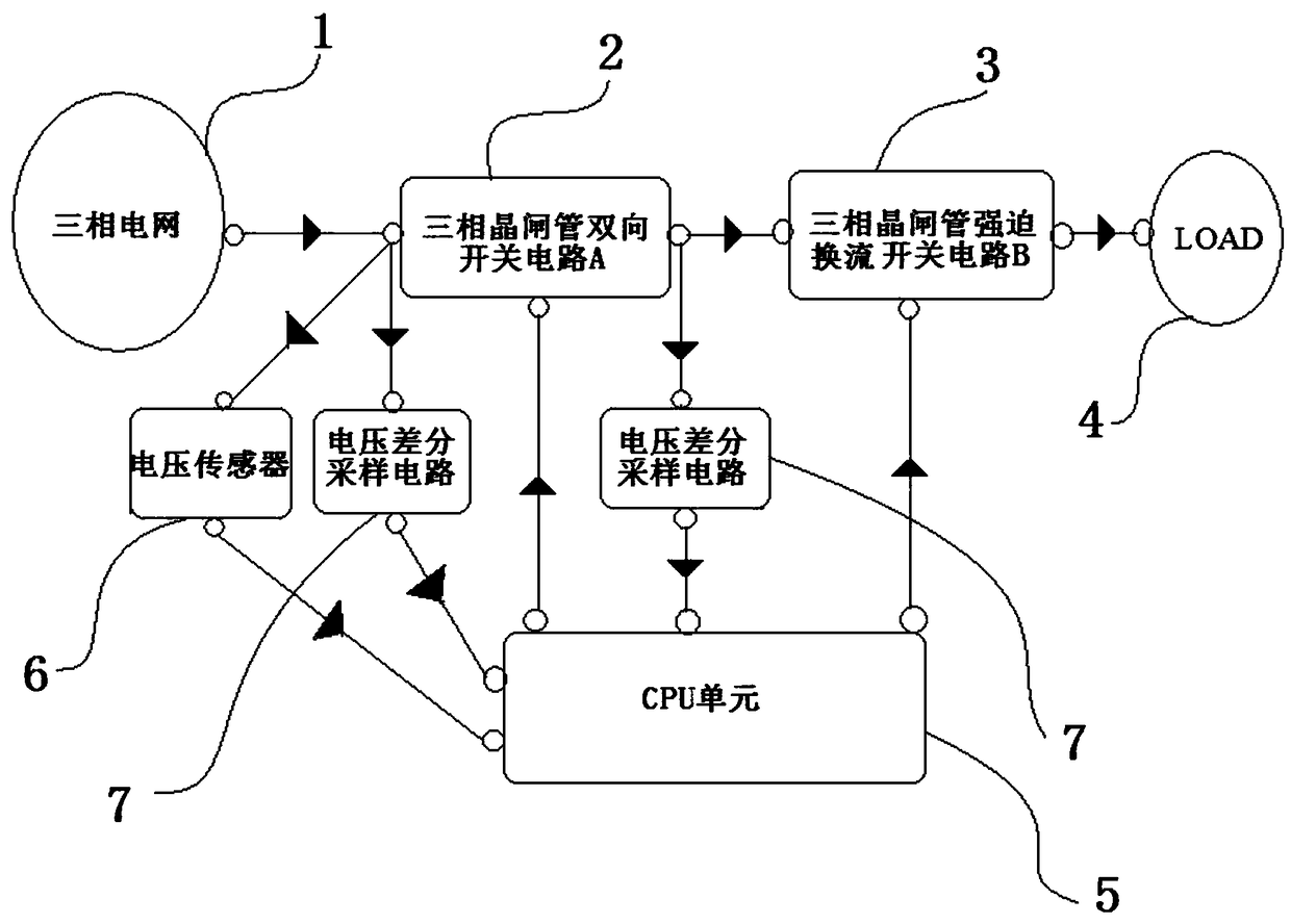
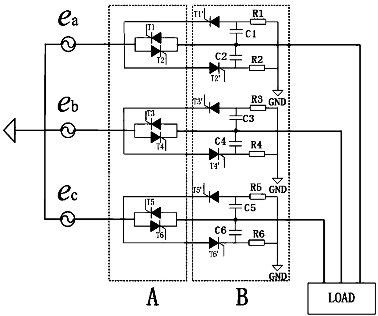
[0035] figure 1 It is an overall circuit connection schematic diagram of a preferred embodiment of a microgrid three-phase thyristor fast switch of the present invention. The present invention proposes a microgrid three-phase thyristor fast switch, including a three-phase power grid 1 and a load LOAD4, characterized in that Including a three-phase thyristor bidirectional switch circuit A2, a three-phase thyristor forced commutation switch circuit B3, and a CPU unit 5, the three-phase power grid 1 is connected to the input end of the three-phase thyristor bidirectional switch circuit A2, and the three-phase thyristor The output terminal of the bidirectional switch circuit A2 is connected to the ...


PUM


Abstract

The invention discloses a micro-grid three-phase thyristor fast switch and a control method. The fast switch comprises a three-phase grid and a LOAD, and further comprises a three-phase thyristor bidirectional switch circuit A, a three-phase thyristor forced commutation switch circuit B and a CPU. The three-phase grid is connected to an input end of the three-phase thyristor bidirectional switch circuit A; an output end of the three-phase thyristor bidirectional switch circuit A is connected to the LOAD through the three-phase thyristor forced commutation switch circuit B; the CPU is separately connected to a control end of the three-phase thyristor bidirectional switch circuit A and a control end of the three-phase thyristor forced commutation switch circuit B. According to the micro-gridthree-phase thyristor fast switch and the control method, a forced turn-off function is realized; the requirements of fast and off-grid switching of a micro-grid system is met; and a conduction failure problem that may be caused by a voltage zero-crossing is taken into account, so that the turn-off function of the thyristor switch is realized, and a problem that a capacitor is discharged to the micro-grid caused by the conduction failure is effectively solved.

Description

technical field [0001] The invention relates to a fast switch of a three-phase thyristor in a micro-grid and a control method thereof, and belongs to the technical field of fast switches of a micro-grid. Background technique [0002] Due to the rapidly growing demand for electricity, the depletion of traditional energy sources, and the increasingly prominent contradictions between environmental pollution, the development of new energy and renewable energy has become an inevitable choice to solve the contradictions between global energy shortages and environmental protection. Energy is included in the national development plan. Compared with the traditional large power grid, distributed power generation has the characteristics of green and pollution-free, flexible installation location, high energy utilization rate, and reduced transmission loss energy of long lines. However, its own problems are gradually exposed, such as distributed power supply control is difficult, unsta...

Claims


Application Information

Patent Timeline
Patent Type & Authority Applications(China)
IPC IPC(8): H02J3/00
CPCH02J3/00
Inventor 刘嘉程益德刘淮通刘柱云
Owner NANJING GUODIAN NANZI POWER GRID AUTOMATION CO LTD
Learn More