Charging pile system
A technology of charging pile system and charging device, which is applied in the direction of current collectors, electric vehicles, electrical components, etc., can solve the problems of low power conversion efficiency, achieve the effects of no high-frequency electromagnetic radiation, easy process realization, and improve power conversion efficiency
- Summary
- Abstract
- Description
- Claims
- Application Information
AI Technical Summary
Problems solved by technology
Method used
Image

Examples
Embodiment 1
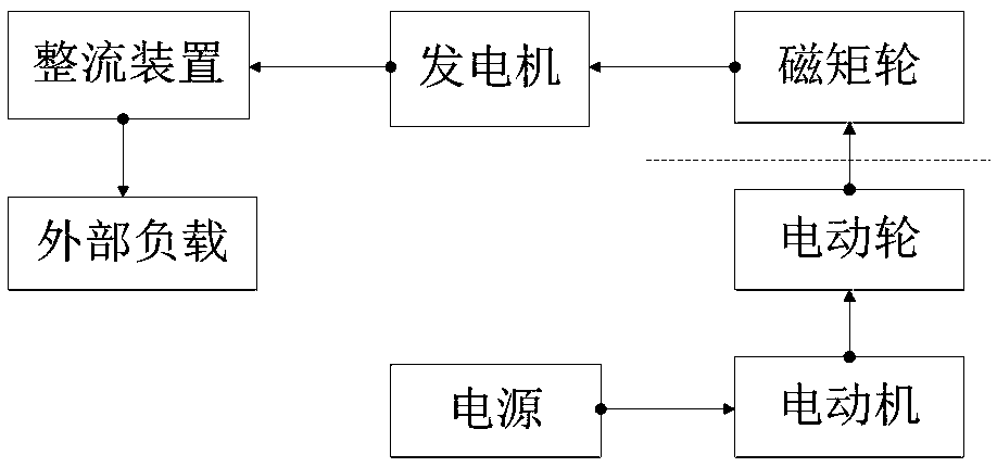
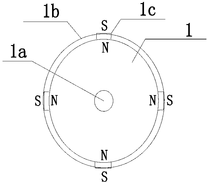
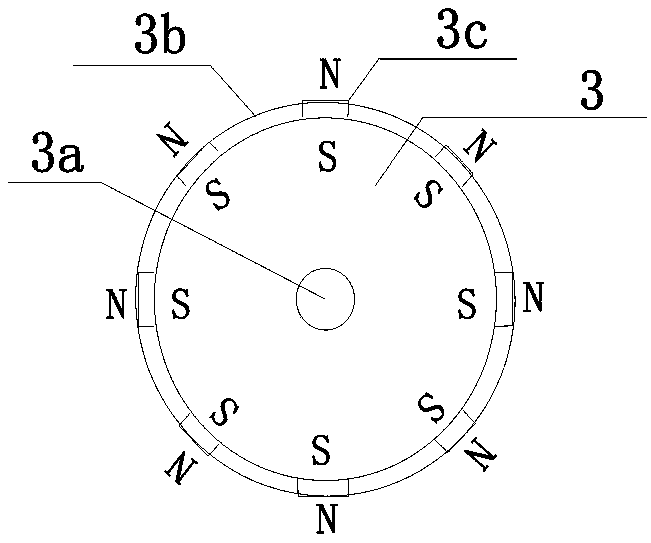
[0053] A charging pile system, including electric wheel 1, motor 2, magnetic moment wheel 3, generator 5 and rectification device; motor 2 is a rotary AC motor with a nominal 220V, and its power control terminal is connected to a conventional civilian 220V city network AC power supply The rotating shaft of the motor 2 is fixedly connected with the rotating shaft 1a of the electric wheel 1, and drives the electric wheel 1 to rotate in a shaft transmission mode; Figure 4 As shown (static diagram): the material of the electric wheel 1 is plastic steel, and 4 moving magnets 1c are evenly arranged around the wheel rim 1b at intervals, and the N poles of the moving magnets face the rotating shaft 1a, and the S poles face the outer edge (such as figure 2 As shown), the arc distance between the outer edges of the moving magnet is m; the material of the magnetic moment wheel 3 is a non-magnetic alloy, and eight rotating magnets 3c are evenly arranged around the wheel rim 3b, and the S p...
Embodiment 2
[0057] All the magnetic pole directions of the electric wheel 1 described in Embodiment 1 are replaced, that is, the S pole of the moving magnet 1c arranged around the rim 1b of the electric wheel 1 faces the rotating shaft 1a, and the N pole faces the outer edge; the rest of the components and structures remain unchanged.
[0058] In this embodiment, the magnetic poles of the moving magnet 1c of the electric wheel 1 and the rotating magnet 3c of the magnetic moment wheel 3 are arranged in the same way, all of which are S poles facing the rotating shaft 3a and N poles facing the outer edge, so that the electric wheel 1 and The force shown by the change of the magnetic field distribution state between the rotating magnets 3c is mutual repulsion; when the city power grid supplies power to the motor 2 to drive the electric wheel 1 to rotate, the rotation of the moving magnet 1c around the axis 1a will generate a magnetic force along the rotating magnet 3c The magnetic repulsion fo...
Embodiment 3
[0060] The charging pile system of Embodiment 1 is technically deformed, and two magnetic moment wheels 3 are set. The rotating magnets 3c on the rims 3b of the two magnetic moment wheels are distributed in the same way, and the rotating shafts 3a of the two magnetic moment wheels are respectively fixed and installed on the same On the rotating shaft, it can be regarded as a magnetic moment wheel 3 with reference to the shaft longitudinal direction; at the same time, two electric wheels 1 are respectively arranged corresponding to the two magnetic moment wheels 3, and the moving magnets 1c on the two electric wheel rims 1b have the same distribution, The rotating shafts 1a of the two electric wheels are respectively fixedly installed on the same rotating shaft, so that they can be regarded as one electric wheel 1 with reference to the shaft longitudinal direction. During installation, the plane centerlines 11 of the two electric wheels 1 coincide with the plane centerlines 33 o...
PUM
 Abstract
Description
Claims
Application Information
 - R&D
- Intellectual Property
- Life Sciences
- Materials
- Tech Scout
- Unparalleled Data Quality
- Higher Quality Content
- 60% Fewer Hallucinations
Browse by: Latest US Patents, China's latest patents, Technical Efficacy Thesaurus, Application Domain, Technology Topic, Popular Technical Reports.
© 2025 PatSnap. All rights reserved.Legal|Privacy policy|Modern Slavery Act Transparency Statement|Sitemap|About US| Contact US: help@patsnap.com