Wireless energy transmission method for power grid high potential monitoring equipment oriented sensor

A technology for wireless energy transmission and monitoring equipment, used in current collectors, battery circuit devices, electric vehicles, etc., can solve the problems of large volume and weight, poor maintainability, and high damage rate, and achieves reduced complexity, reduced operation difficulty, The effect of ensuring transmission efficiency

Inactive Publication Date: 2018-11-23
NANJING UNIV OF AERONAUTICS & ASTRONAUTICS
View PDF4 Cites 5 Cited by
  • Summary
  • Abstract
  • Description
  • Claims
  • Application Information

AI Technical Summary

Problems solved by technology

In the engineering application of transmission line monitoring equipment, these power supply methods are mainly manifested in the following aspects: ① poor reliability and high damage rate; ② poor maintainability; ③ large volume and weight

Method used


Image

  • Wireless energy transmission method for power grid high potential monitoring equipment oriented sensor
  • Wireless energy transmission method for power grid high potential monitoring equipment oriented sensor
  • Wireless energy transmission method for power grid high potential monitoring equipment oriented sensor

Examples


Embodiment Construction

[0024] The wireless energy transmission method for grid high potential monitoring equipment sensors proposed by the present invention, in order to make the purpose, technical solution and effect of the present invention clearer and clearer, and the present invention is further described in detail with reference to the accompanying drawings.

[0025] Below in conjunction with accompanying drawing, the technical scheme mentioned in the present invention is described in detail:

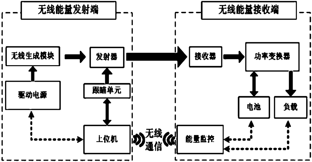
[0026] In order to meet the energy supply requirements of the sensors of the grid high potential monitoring equipment, the present invention mainly adopts a wireless energy transmission unit, a tracking and aiming unit and an energy monitoring unit to realize.

[0027] Wireless Energy Transfer Unit

[0028] There are many ways to transmit wireless energy, such as laser, microwave, ultrasonic and so on. The choice of energy transmission mode is also a key factor restricting the overall efficiency of the ...


PUM


Abstract

The invention discloses a wireless energy transmission method for a power grid high potential monitoring equipment oriented sensor, and belongs to the field of power grid high potential monitoring. The method comprises the following steps: (1) before energy is supplied for the sensor, starting a tracking aiming unit of the system, and beginning to automatically search a wireless energy receiver ata receiving end; (2) after the wireless energy receiver is aimed by a wireless transmitter, increasing power to start energy transmission, collecting fed-back positional information parameters of thewireless energy receiver in real time according to an upper computer by the tracking aiming unit in the period to constantly adjust the posture, and thus completing real-time tracking energy transmission at the receiving end; and (3) in the energy transmission period, carrying out real-time monitoring on the electric quantity of a storage battery at the receiving end by the energy monitoring unit, and controlling the turning-on and turning-off of a driving source according to the electric quantity. Efficient and continuous energy supply for the monitoring equipment oriented sensor is realized, and the energy supply operation of workers for the monitoring equipment sensor is completed in a safe region in a remote non-contact mode.

Description

technical field [0001] The invention relates to a wireless energy transmission method for a sensor of a high potential monitoring equipment of a power grid, and belongs to the field of high potential monitoring of a power grid. Background technique [0002] With the development of power system automation and smart grid, real-time monitoring of high-voltage power equipment is becoming increasingly important, and the application of smart electronic devices and monitoring sensors in power transmission and transformation equipment is becoming more and more extensive. In order to accurately monitor various physical quantities of electrical equipment, a large number of sensor nodes of various types will be densely distributed in the area to be measured. Usually, sensors and electronic equipment are powered by low-voltage DC, but in the complex working environment of medium and high-voltage electrical equipment, the conventional method of artificially replenishing sensor node energ...

Claims


Application Information

Patent Timeline
Patent Type & Authority Applications(China)
IPC IPC(8): H02J50/90H02J50/15H02J50/20H02J50/30H02J7/00
CPCH02J7/025H02J50/15H02J50/20H02J50/30H02J50/90
Inventor 金科梁欢张冉杨天乙
Owner NANJING UNIV OF AERONAUTICS & ASTRONAUTICS
Why Eureka
Try Eureka