
Magnetic pole staggered power generation device

A power generation device and magnetic pole technology, applied in the direction of electromechanical devices, electrical components, etc., can solve the problems of difficulty in increasing the operating speed of power generation devices, affecting the frequency of cutting, and low energy conversion rates.

Inactive Publication Date: 2018-11-23
YUZEN SUSTAINABLE ENERGY PTE LTD +1
View PDF4 Cites 0 Cited by
  • Summary
  • Abstract
  • Description
  • Claims
  • Application Information

AI Technical Summary

Problems solved by technology

[0003] When the aforementioned power generating device is in operation, when the coil of the coil group is connected to a load, a current will be generated, and the coil group will be induced and magnetized to become an electromagnet, so that the two ends of the coil group and the magnetic parts of the magnetic group will have a double magnetic attraction phenomenon, and Its magnetic attraction force is opposite to the direction of motion and is reluctance, so there will be kinetic energy loss caused by accretion reluctance under load, so it is difficult to increase the operating speed of traditional power generation devices, which seriously affects the cutting frequency and lowers the energy conversion rate. ;
[0004] In other words, due to the influence of double magnetic resistance on the existing power generation device, it causes kinetic energy loss, slows down its operation speed and reduces its cutting frequency, and there is a problem of wasting energy, which reduces the overall energy conversion rate. Therefore, how to solve the aforementioned problems, Urgently needed to be developed by the industry
[0005] In view of this, the inventor of the present invention has conducted in-depth discussions on the problems faced by the aforementioned existing power generation devices in the application, and actively sought solutions through years of research and development experience in related industries. After continuous efforts in research and trial production, finally Successfully developed a magnetic pole dislocation power generation device to overcome the loss and waste caused by the increased magnetic resistance of the existing ones

Method used


Image

  • Magnetic pole staggered power generation device
  • Magnetic pole staggered power generation device
  • Magnetic pole staggered power generation device

Examples


Embodiment Construction

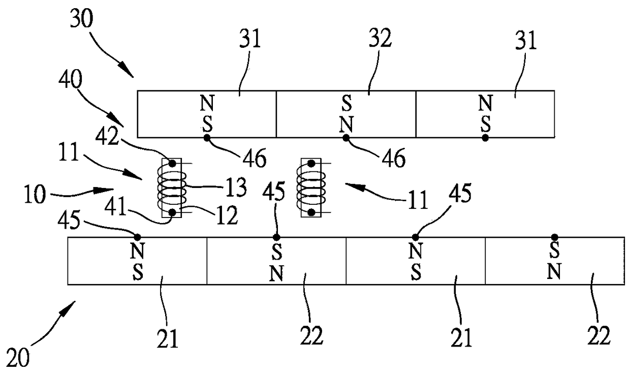
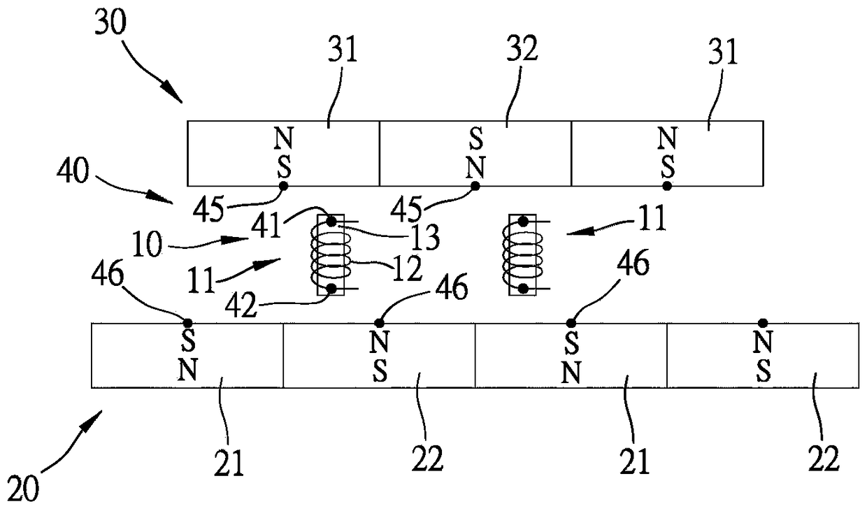
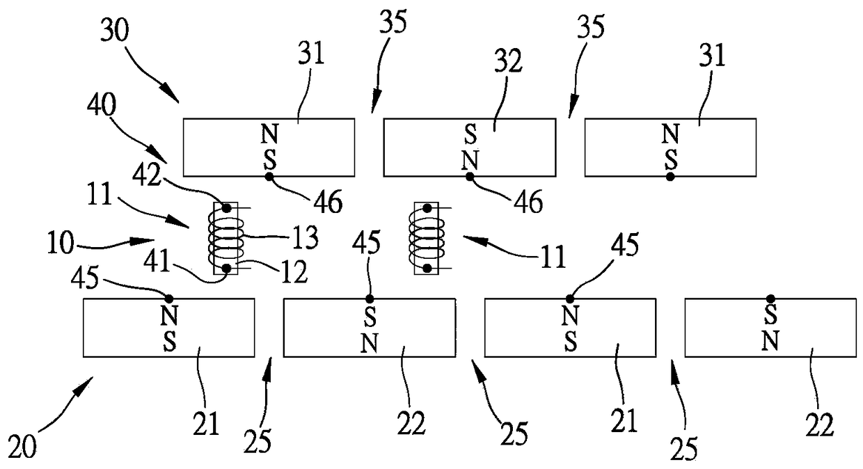
[0033] In order to further understand the structure, features and other purposes of the present invention, the following are preferred embodiments of the present invention, and are described in detail with reference to the drawings, so that those skilled in the art can implement them.

[0034] The present invention is a magnetic pole dislocation power generation device. In the specific embodiments of the present invention and its components illustrated in the accompanying drawings, all references to front and rear, left and right, top and bottom, upper and lower, and horizontal and vertical , are used for convenience of description only, and do not limit the present invention, nor limit its components to any position or direction in space. The dimensions specified in the drawings and description can be changed according to the design and requirements of the specific embodiments of the present invention without departing from the patent scope of the present invention.

[0035] ...


PUM


Abstract

The invention discloses a magnetic pole staggered power generation device. The magnetic pole staggered power generation device is provided with an induction coil group; a first magnetic group and a second magnetic group which can synchronously move relative to each other are arranged on the two sides of the induction coil group respectively; the first magnetic group is formed by at least one firstmagnetic piece and second magnetic piece which are magnetized in the movement direction and are connected at equal intervals in series in a different-pole arrangement mode; the second magnetic groupis formed by a third magnetic piece and a fourth magnetic piece which are magnetized in the movement direction and are connected at equal intervals in series in a different-pole arrangement mode; thethird and fourth magnetic pieces and the first and second magnetic pieces are arranged in a staggered mode relatively; a load switch group for selectively performing power-on on the induction coil group or not is arranged between the induction coil group and the first magnetic group and between the induction coil group and the second magnetic group separately; therefore, the magnetic stress, relative to the induction coil group, of the first magnetic group and the second magnetic group can be mutually eliminated, so that the kinetic energy loss is reduced, and the cutting frequency is effectively increased; and in addition, most of the magnetic lines of force flows through the coil part, so that the cutting quantity can be greatly increased, and the energy conversion efficiency can be effectively improved.

Description

technical field [0001] The present invention relates to the field of electromagnetic technology for energy conversion, specifically refers to a magnetic pole dislocation power generation device that can eliminate reluctance, increase cutting frequency, effectively guide magnetic flux, and increase the number of cutting, so as to improve its energy conversion efficiency . Background technique [0002] A general generating device is composed of an induction group and a magnetic group, wherein the induction group is provided with at least one coil on at least one magnetizer, and the magnetic group is provided with two magnetic parts at both ends of the induction group axis, and the two magnetic parts The opposite magnetic poles are arranged oppositely, and the magnetic group and the induction group can be defined as the rotor and the stator respectively, and through relative linear or rotational motion, the coil of the induction group generates voltage due to the magnetic field...

Claims


Application Information

Patent Timeline
IPC IPC(8): H02K35/02
CPCH02K35/02
Inventor 许永顺许名俊许文毓
Owner YUZEN SUSTAINABLE ENERGY PTE LTD
Learn More