Supercharge Your Innovation With Domain-Expert AI Agents!

friction belt

A technology of friction transmission belts and mass parts, which is applied in the direction of transmission belts, V-belts, belts/chains/gears, etc., can solve the problems of reduced bending fatigue resistance, durability (reduced life, belt cannot move smoothly, etc.), and achieve inhibition Abrasion, improvement of bending fatigue resistance, effect of suppressing peeling or cracking

Active Publication Date: 2020-04-07
MITSUBOSHI BELTING LTD
View PDF20 Cites 0 Cited by
  • Summary
  • Abstract
  • Description
  • Claims
  • Application Information

AI Technical Summary

Problems solved by technology

[0008] However, from the viewpoint of formulation design of such a rubber composition, there is a concern that the following problems (1) to (4) may occur with belt running in a high-load environment, resulting in a reduction in durability (life)
[0009] (1) When the adhesiveness between the core wire and the adhesive rubber layer is low, peeling occurs between the core wire and the adhesive rubber layer
[0010] (2) When the friction coefficient of the contact surface (transmission surface) of the belt with the pulley is high, the belt cannot move smoothly, so the belt is easily deformed (especially buckling called dent)
[0018] However, even if this adhesive rubber layer is used, it is not enough to meet the further requirements of the high-load environment in recent years, and if the hardness is increased excessively by increasing the compounding amount of bismaleimide, the bending fatigue resistance will decrease.
[0019] That is, in the prior art, as in the belts of Patent Documents 1 to 4, although solutions to various problems have been proposed, it cannot be said that all of them can meet the requirements for withstanding severe operation in a high-load environment such as a transmission belt. characteristic
In detail, in the prior art, it has not been possible to maintain the adhesiveness of the adhesive rubber layer and the core wire while ensuring the mechanical properties (satisfying resistance to interfacial peeling (dispersion of shear stress), abrasion resistance, etc.) ), and a special product design that can also suppress the wear of the pulley

Method used

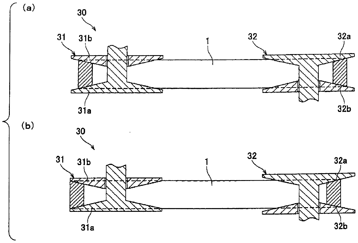
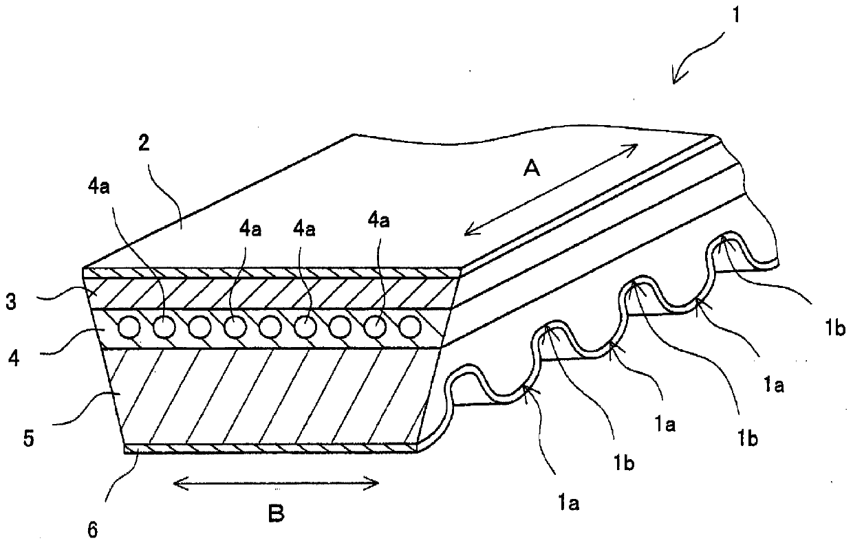
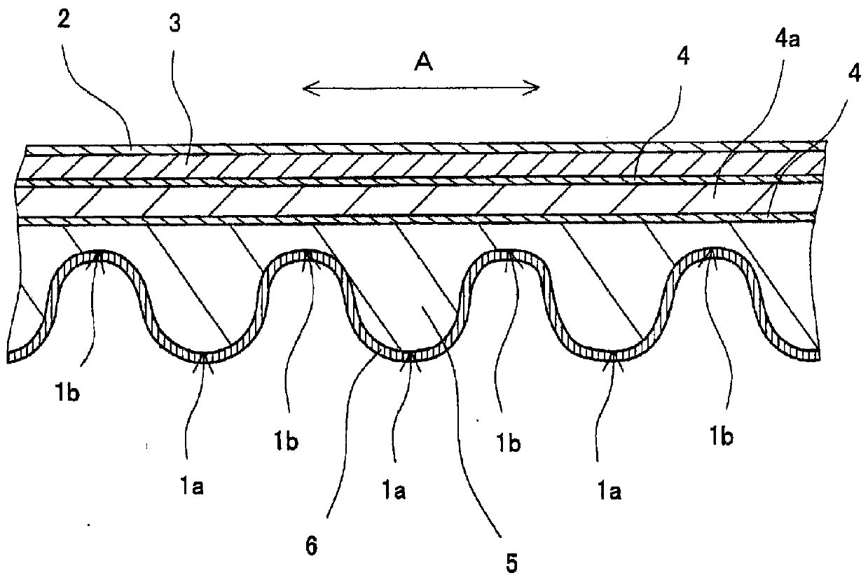

Image

  • friction belt
  • friction belt
  • friction belt

Examples


Embodiment 1~8 and comparative example 1~4

[0163] (formation of rubber layer)

[0164] The rubber compositions in Table 1 (adhesive rubber layer) and Table 2 (compressed rubber layer and stretched rubber layer) were respectively kneaded using a known method such as a Banbury mixer, and the kneaded rubber was obtained from calendering. The rolled rubber sheets (sheets for the adhesive rubber layer, sheets for the compressed rubber layer, and sheets for the stretched rubber layer) were produced by passing the rollers. In addition, Table 1 shows the physical properties of the vulcanized rubber for the rubber composition used for the adhesive rubber layer.

[0165] [Table 1]

[0166] Table 1 (adhesive rubber layer)

[0167]

[0168] [Table 2]

[0169] Table 2 (compressed rubber layer and extended rubber layer)

[0170]

[0171] (Adhesive treatment of core wire)

[0172] After immersing the core wire in the first treatment agent (pretreatment liquid) shown in Table 3, heat treatment was performed at 180° C. for 4...

Embodiment 4

[0195] Example 4 is a friction transmission belt in which the amount of carbon black in the adhesive rubber layer is as high as 70 parts by mass. The core wire was slightly peeled off on the side of the belt after running for 24 hours, but it was not a practical problem. In Example 5, the ratio of silica in the adhesive rubber layer was as low as 4 parts by mass relative to 100 parts by mass of carbon black, and the peeling of the core wire was slightly observed on the side of the belt after 24 hours of running, but it was There is no problem practically.

Embodiment 6

[0196] Example 6 is a friction transmission belt containing 10 parts by mass of silica in the outer coating layer. The core wire was slightly peeled off on the side of the belt after running for 24 hours, but it was not a practical problem. Example 8 is a friction transmission belt containing 60 parts by mass of silica in the outer coating layer. The core wire was slightly peeled off on the side of the belt after running for 24 hours, but it was not a practical problem. Considering the results of Examples 6 to 8, it turned out that the peeling of the core wire occurred regardless of whether the amount of silica compounded in the overcoat layer was too small or too large.


PUM

PropertyMeasurementUnit
hardnessaaaaaaaaaa
hardnessaaaaaaaaaa
particle diameteraaaaaaaaaa

Abstract

The present invention relates to a friction transmission belt having an adhesive rubber layer in contact with at least a part of a core extending along the belt longitudinal direction, wherein the adhesive rubber layer is made of a first material containing a rubber component and a filler. Vulcanized rubber composition, the above-mentioned filler contains 30 mass parts or more of carbon black and 0.1 to 15 mass parts of silica with respect to 100 mass parts of rubber components, and the above-mentioned core has a second layer composed of rubber components and silica on the surface. An overcoat layer formed of a divulcanized rubber composition.

Description

technical field [0001] The present invention relates to friction transmission belts such as V-belts and V-ribbed belts whose friction transmission surfaces are inclined to form a V shape. Background technique [0002] Conventionally, friction transmission belts such as V-belts, ribbed belts, and flat belts are known as transmission belts for transmitting power. A V-belt or V-ribbed belt that forms a friction transmission surface (V-shaped side) at a V-shaped angle applies tension between the driving pulley and the driven pulley and hangs it, and the V-shaped side contacts the V-shaped groove of the pulley The state is rotating and walking between two axes. In this process, power is transmitted by utilizing the energy accompanying the friction generated by the thrust between the V-shaped side surface and the V-shaped groove of the pulley. In these friction transmission belts, a core is embedded in the rubber body (between the compression rubber layer and the extension rubbe...

Claims


Application Information

Patent Timeline
Patent Type & Authority Patents(China)
IPC IPC(8): F16G1/08C08K3/04C08K3/36C08L21/00F16G5/06F16G5/20
CPCC08K3/04C08K3/36F16G1/08F16G5/06F16G5/20C09J111/00C08L11/00F16G5/04C09J7/24C09J7/30B32B2307/746C09J11/04C09J2411/00C09J2411/006B32B3/30B32B5/02B32B25/02B32B25/042B32B25/10B32B25/16B32B2260/021B32B2260/048B32B2262/0261B32B2262/0276B32B2264/102B32B2264/108B32B2307/584B32B2433/04F16G5/08
Inventor 石黑久登友田拓也
Owner MITSUBOSHI BELTING LTD
Features
  • R&D
  • Intellectual Property
  • Life Sciences
  • Materials
  • Tech Scout
  • Unparalleled Data Quality
  • Higher Quality Content
  • 60% Fewer Hallucinations
Learn More