
Three-vehicle-model automatic turnover and position-changing machine

A technology of automatic flipping and positioner, applied in auxiliary devices, auxiliary welding equipment, welding/cutting auxiliary equipment, etc., can solve the problems of increasing design cost and design difficulty, increasing product changing time, increasing switching time, etc. Shorten the welding cycle, ensure the repeated positioning accuracy of the equipment, and ensure the welding quality and effect.

Pending Publication Date: 2018-11-27
天永锂电自动化设备(太仓)有限公司
View PDF7 Cites 0 Cited by
  • Summary
  • Abstract
  • Description
  • Claims
  • Application Information

AI Technical Summary

Problems solved by technology

[0002] Based on the principle of servo motor driving the reducer, the field of body-in-white and chassis welding is applied to realize fast and flexible switching of multiple models. This function is of great significance for automobile production lines. However, all current switching equipment for multiple models has defects of low precision and efficiency. , or the equipment structure is complex, resulting in higher manufacturing costs and longer product changeover time
[0003] At present, the three-model switching equipment adds many mechanisms to the same BASE to realize the conversion of different models. This switching method needs to consider the movement trajectory of each mechanism. It can be used when the products are not very different. When switching between products with large differences in shape , it is very difficult, which increases the design cost and design difficulty a lot. When the product is switched, it needs PLC to control all the actions of the model, which will increase the switching time.

Method used


Image

  • Three-vehicle-model automatic turnover and position-changing machine
  • Three-vehicle-model automatic turnover and position-changing machine
  • Three-vehicle-model automatic turnover and position-changing machine

Examples


Embodiment Construction

[0017] The following will clearly and completely describe the technical solutions in the embodiments of the present invention with reference to the accompanying drawings in the embodiments of the present invention. Obviously, the described embodiments are only some, not all, embodiments of the present invention. Based on the embodiments of the present invention, all other embodiments obtained by persons of ordinary skill in the art without making creative efforts belong to the protection scope of the present invention.

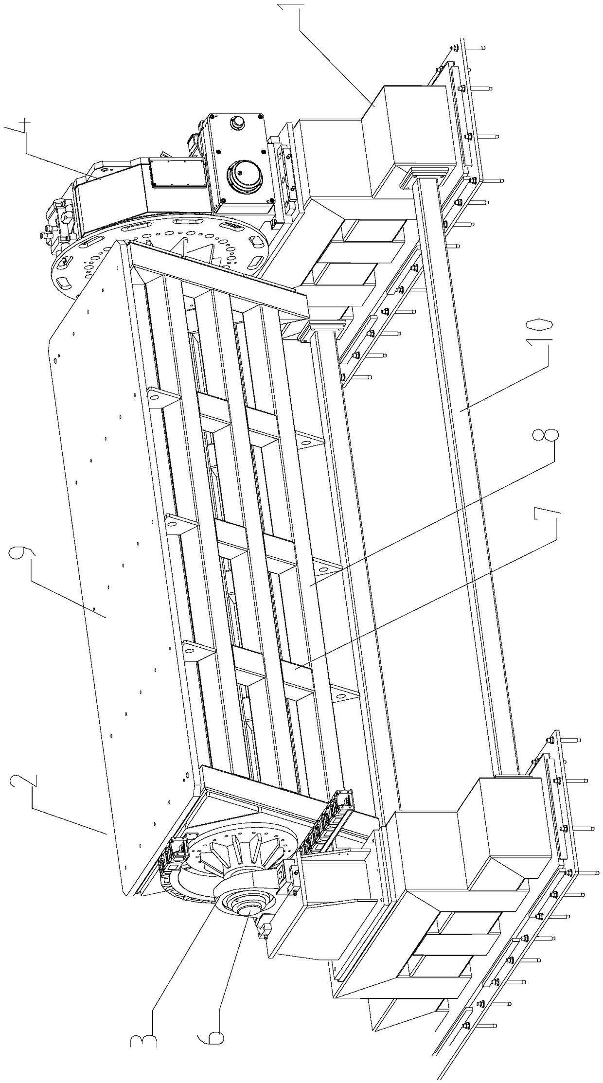
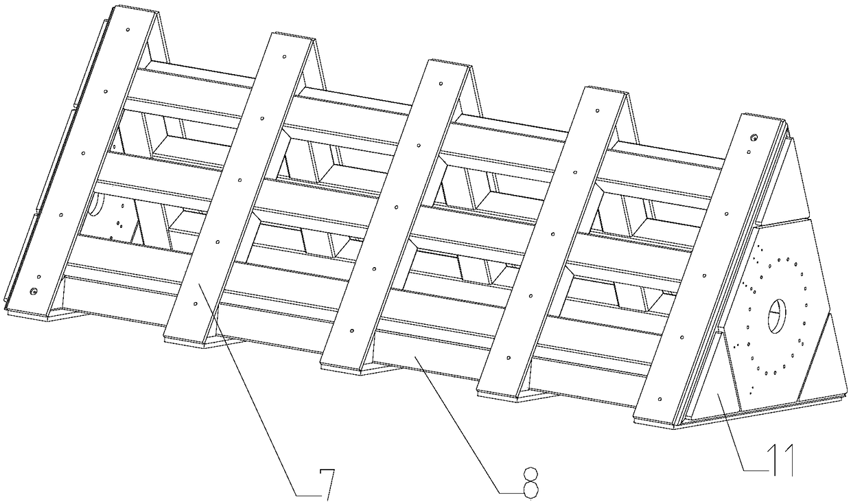
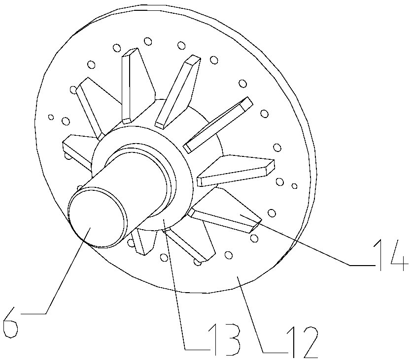
[0018] An automatic turning and shifting machine for three vehicle types, comprising: fixed brackets 1 on both sides, a three-sided platform frame 2 fixed on the fixed brackets 1 on both sides, a bearing seat 3 and a reducer 4. The three-sided platform skeleton 2 is a three-sided column body, the side faces of the three-sided column body are interconnected operating surfaces, the bottom surface of the three-sided column body is a mounting plate, and the center ...


PUM


Abstract

The invention discloses a three-vehicle-model automatic turnover and position-changing machine. The machine comprises fixed supports at the two sides, three-sided platform frameworks fixed to the fixed supports at the two sides, a bearing pedestal and a speed reducer; the three-sided platform frameworks are three-sided column bodies, the side faces of the three-sided column bodies are operating surfaces mutually connected, a mounting plate is arranged on the bottom face of each three-sided column body, a bearing is installed in the center of the bottom face of each mounting plate, a rotary shaft is installed in the center of each bearing and installed on the bearing pedestal, and the bearing pedestal is fixed to the fixed supports at the two sides; the other end of the rotary shaft is connected with the speed reducer, and the speed reducer is connected with a servo motor. By means of the three-vehicle-model automatic turnover rotary platform, compared with other types of three-vehicle-model switching equipment, the production cost is reduced, the occupied area of a plant is reduced, the equipment utilization rate is increased, and it is guaranteed that the repeated positioning accuracy of the equipment is stable.

Description

technical field [0001] The invention relates to an automatic turning and shifting machine for three vehicle types, which belongs to positioner equipment for automatic turning and switching welding of three vehicle types. Background technique [0002] Based on the principle of servo motor driving the reducer, the field of body-in-white and chassis welding is applied to realize fast and flexible switching of multiple models. This function is of great significance for automobile production lines. However, all current switching equipment for multiple models has defects of low precision and efficiency. , or the equipment structure is complicated, resulting in higher manufacturing costs and increasing the time for product changeover. [0003] At present, the three-model switching equipment adds many mechanisms to the same BASE to realize the conversion of different models. This switching method needs to consider the movement trajectory of each mechanism. It can be used when the pr...

Claims


Application Information

Patent Timeline
Patent Type & Authority Applications(China)
IPC IPC(8): B23K37/047
CPCB23K37/047
Inventor 荣俊林
Owner 天永锂电自动化设备(太仓)有限公司
Learn More