Heat pump drying system

A heat pump drying and heat pump system technology, applied in drying, dryer, fluid heater and other directions, can solve the problems of air pollution, heat waste, unfavorable sustainable development of the national economy, etc., and achieve recycling and enhancement effects Effect

Pending Publication Date: 2018-11-27
广东高而美制冷设备有限公司
View PDF0 Cites 2 Cited by
  • Summary
  • Abstract
  • Description
  • Claims
  • Application Information

AI Technical Summary

Problems solved by technology

This traditional heating method not only pollutes the air, but also wastes energy, which is not conducive to the sustainable development of the national economy.
In addition, most

Method used


Image

  • Heat pump drying system
  • Heat pump drying system
  • Heat pump drying system

Examples


Example Embodiment

[0017] The present invention will be further described below in conjunction with specific examples.

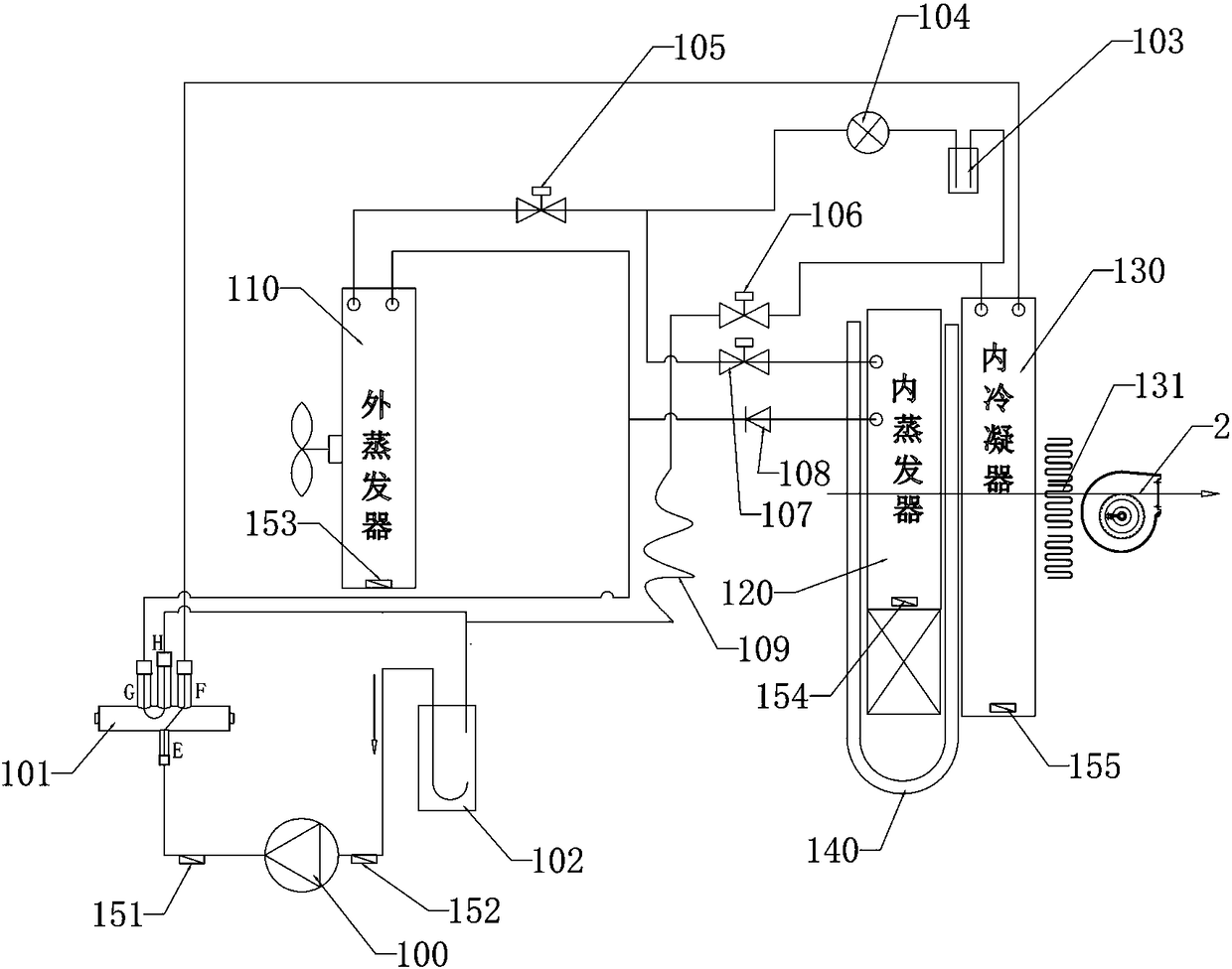
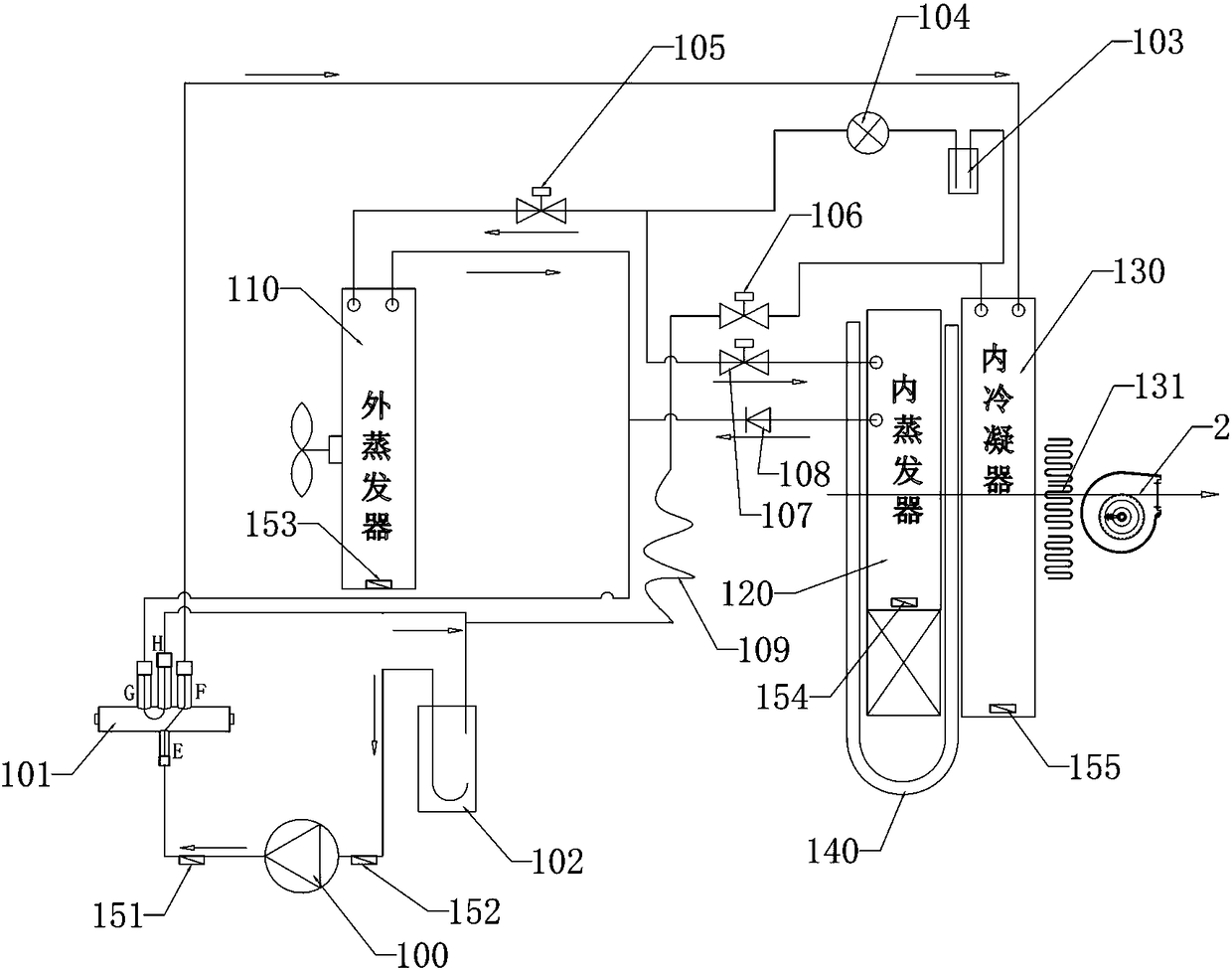
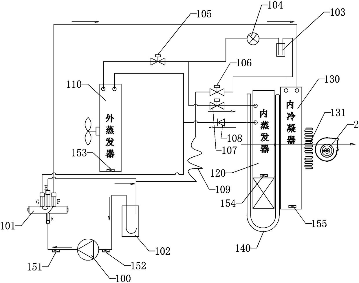
[0018] See attached figure 1 to attach Figure 4 As shown, in this embodiment, a heat pump drying system includes a heat pump system, a heat pipe 140 unit and an auxiliary heating unit 131, wherein the heat pump system includes a compressor 100, a four-way valve 101, and an outdoor heat exchanger 110 , internal evaporator 120, internal condenser 130, vapor-liquid separator 102, liquid reservoir 103, liquid injection solenoid valve 106, throttling unit 109, expansion valve 104, first solenoid valve 105, second solenoid valve 107, the first Three solenoid valves and the first one-way valve 108; the four-way valve 101 includes E, F, G and H ports, wherein, the ports E and F of the four-way valve 101 communicate in the four-way valve 101 and the ports G and The interface H communicates in the four-way valve 101; the output port of the compressor 100 communicates with the interfa...


PUM


Abstract

The invention discloses a heat pump drying system comprising a heat pump system. The heat pump system includes a compressor, a four-way valve, an outdoor heat exchanger, an inner evaporator and an inner condenser. A port E of the four-way valve is communicated with an output port of the compressor, and a port F is communicated with an inlet of the inner condenser. A port H of the four-way valve iscommunicated with an input port of the compressor, an outlet of the inner condenser is communicated with the outdoor heat exchanger and an inlet of the inner evaporator, and preset low-temperature air performs heat exchange with the inner evaporator and the inner condenser and then is sent out. A circular air passage loop is formed by a heat pump chamber and a drying chamber, so that recycling ofheat is achieved; at the same time, by setting pre-absorption of heat and preheating functions of a heat pipe, dehumidification and heating effects are enhanced in combination with the inner evaporator and the inner condenser.

Description

technical field [0001] The invention relates to the technical field of heat pump drying systems, in particular to a heat pump drying system. Background technique [0002] Most of the traditional drying techniques in my country use electric heating, coal-fired gas boilers and other heating methods to heat and dry the indoor air and discharge the moisture contained in the material to the outside, while supplementing part of the drying fresh air. This traditional heating method not only pollutes the air, but also wastes energy, which is not conducive to the sustainable development of the national economy. In addition, most of the high-temperature and high-humidity air in the existing dryer is directly discharged through the air outlet, which leads to serious waste of heat and lack of heat recycling. Contents of the invention [0003] The purpose of the present invention is to overcome the deficiencies of the prior art and provide a heat pump drying system with high heating e...

Claims


Application Information

Patent Timeline
IPC IPC(8): F26B21/00F26B21/06F24H4/06F24H9/20
CPCF24H4/06F24H9/2064F26B21/001F26B21/06
Inventor 郭庆盛李卓华区国滔
Owner 广东高而美制冷设备有限公司
Why Eureka
Try Eureka