Shunting structure for use in collecting pipe of heat exchange unit of automobile

A heat exchange unit and header technology, which is applied to the heat exchanger shell, indirect heat exchanger, heat exchange equipment, etc., can solve the problems of inconsistent temperature at the outlet, no technical solution found, and uneven heating temperature. , to reduce the detour time, facilitate consistent design management, and improve uniformity

Pending Publication Date: 2018-11-27
TIANJIN SANDEN AUTO AIR CONDITIONING
View PDF0 Cites 5 Cited by
  • Summary
  • Abstract
  • Description
  • Claims
  • Application Information

AI Technical Summary

Problems solved by technology

The uneven distribution of the working fluid in the heat exchange tube leads to the inhomogeneity of the heating temperature of the airflow passing through the surface of the heater core, so that when the airflow is sent into the compartment, the temperature of each air outlet will be inconsistent. Dual temperature zones, The multi-temperature zone air-conditioning system will have a significant temperature difference in the air supply, which will reduce the comfort of the occupants, and in severe cases will cause occupants to complain
[0005] No technical solution similar to this patent was found after searching the prior art

Method used


Image

  • Shunting structure for use in collecting pipe of heat exchange unit of automobile
  • Shunting structure for use in collecting pipe of heat exchange unit of automobile
  • Shunting structure for use in collecting pipe of heat exchange unit of automobile

Examples


Embodiment Construction

[0023] The present invention will be further described in detail below in conjunction with the accompanying drawings and through specific embodiments. The following embodiments are only descriptive, not restrictive, and cannot limit the protection scope of the present invention.

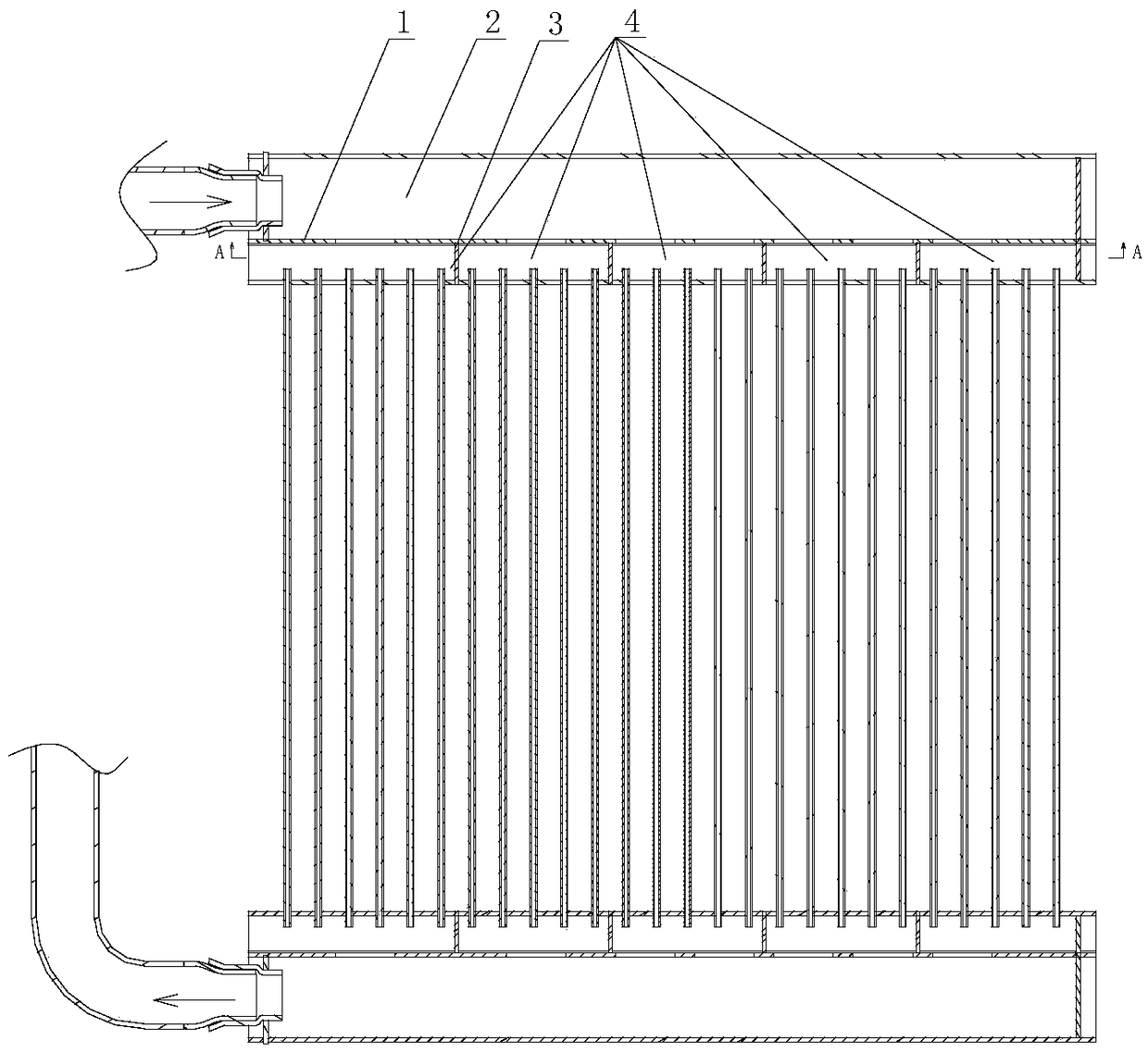
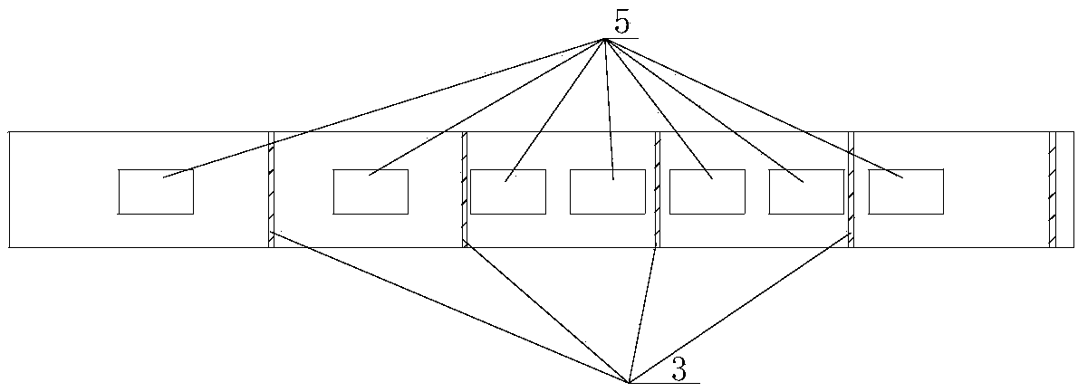
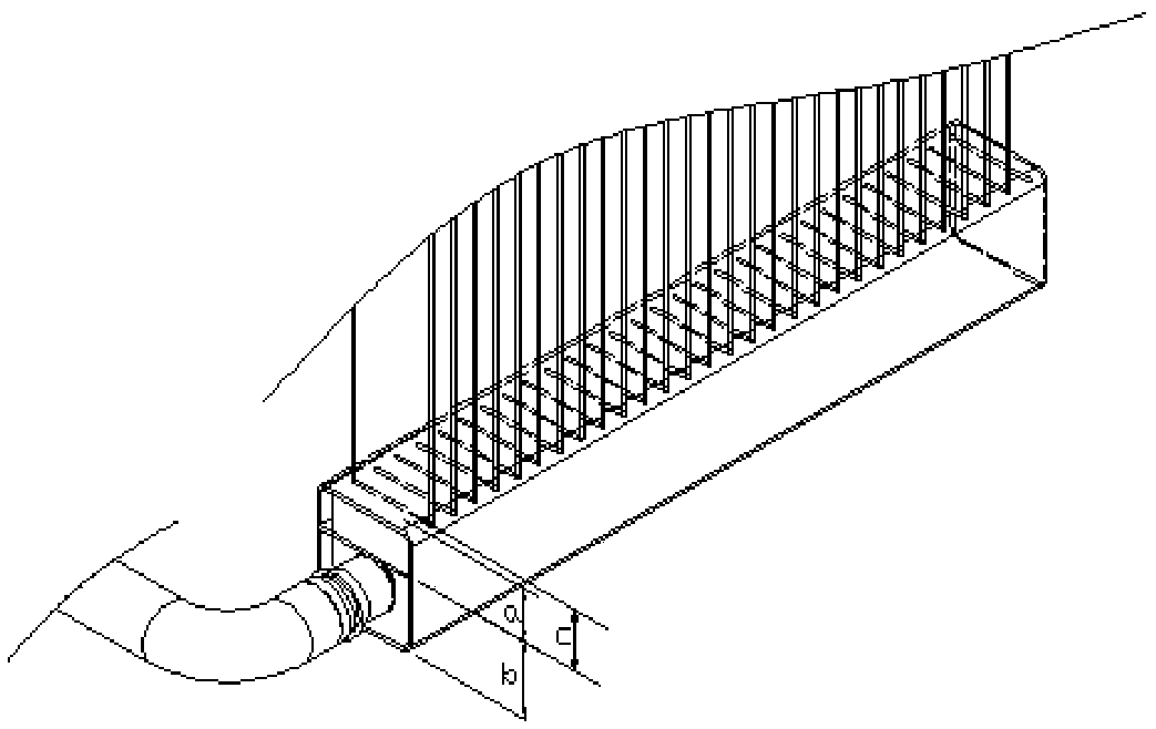
[0024] A kind of shunt structure used in the collector pipe of automobile heat exchange unit, please refer to Figure 1~5 , its invention point is:

[0025] It includes a longitudinal partition plate 1 arranged along the axial direction of the collector. The longitudinal partition plate can be a flat plate or a curved plate. The longitudinal partition plate divides the inner cavity of the collector tube into a first longitudinal cavity 2 and a second longitudinal cavity. The first longitudinal chamber communicates with the working medium inlet, and the second longitudinal chamber communicates with the heat exchange tube. In the second longitudinal chamber, there are a plurality of transverse partiti...


PUM


Abstract

The invention relates to a shunting structure for use in a collecting pipe of a heat exchange unit of an automobile. The shunting structure includes a longitudinal dividing plate disposed along the axial direction of the collecting pipe and dividing an inner cavity of the collecting pipe into a first longitudinal cavity and a second longitudinal cavity. The first longitudinal cavity is communicated with a working medium inlet, the second longitudinal cavity is communicated with heat exchange pipes, a plurality of horizontal dividing plates are distributed in the second longitudinal cavity, andthe second longitudinal cavity is divided into a plurality of shunting areas. The number of the heat exchange pipes corresponding to the plurality of shunting areas is the same, and each shunting area corresponding to the longitudinal dividing plate is provided with shunting holes. In the direction from the liquid inlet end to the other end, in the length range of 0 to X, the circulation areas ofthe shunting holes of the corresponding shunting areas have a gradually increasing trend; in the length range of X to Y, the circulation areas of the shunting holes of the corresponding shunting areas the equal; in the length range of Y 1, the circulation areas of the shunting holes of the corresponding shunting areas have a gradually reduced trend; wherein X is 0.3+/-0.15, and Y is 0.6+/-0.15. The shunting structure improves the evenness of air flow passing across the surface of the heat exchange unit.

Description

technical field [0001] The invention belongs to the technical field of automobile air-conditioning, and relates to a flow diversion technology of a heat exchange unit, in particular to a flow diversion structure used in a collector pipe of an automobile heat exchange unit. Background technique [0002] Common heat exchange units on existing automotive air conditioning systems include heater cores, evaporators, condensers, intercoolers, oil coolers, water tanks, etc. These heat exchange units generally adopt the structure of headers at both ends and multiple sets of heat exchange tubes arranged in parallel, and the heat exchange tubes generally adopt a flat tube structure. During the use of these heat exchange units, there is a common problem to be solved, that is, the problem of uniform distribution of working fluid in multiple sets of heat exchange tubes. [0003] For example, most of the current air conditioners equipped with vehicle models are equipped with heater cores,...

Claims


Application Information

Patent Timeline
Patent Type & Authority Applications(China)
IPC IPC(8): F28F9/02
CPCF28F9/0207F28D2021/008
Inventor 王倩陆新林逄旭陈青梅李扬扬
Owner TIANJIN SANDEN AUTO AIR CONDITIONING
Why Eureka
Try Eureka