Sensing method of fiber grating earth sound sensing system

A sensing system and sensing method technology, applied in the sensing field of fiber grating geoacoustic sensing system, can solve the problems of limited sensitivity improvement, complex preparation process, complex system, etc., and achieve easy industrial production, simple physical structure, The effect of strong system adaptability

Active Publication Date: 2018-11-27
CHINA THREE GORGES UNIV
View PDF7 Cites 0 Cited by
  • Summary
  • Abstract
  • Description
  • Claims
  • Application Information

AI Technical Summary

Problems solved by technology

The existing "point-type" fiber grating sensor fixes the fiber grating on a mechanical structure (such as a cantilever beam), and realizes vibration sensing through mechanical structure transmission. Its sensitivity can basically meet the requirements of debris flow ground acoustic monitoring, but it is difficult to conduct Large-scale multiplexing is not easy to deploy in a wide area; distributed optical fiber sensing technology (such as optical fiber Brillouin sensor (BOTDA), optical fiber Raman sensor (DTS)) can better meet the requirements of large-scale monitoring, However, the detected sensing signal is weak, and the signal needs to be extracted through large-capacity data processing, and the real-time performance is not good.
[0003] In order to improve the sensitivity and multiplexing capability of fiber optic vibration sensors and realize the large-scale and high reliability monitoring of debris flow ground sound, some researchers have introduced the sensing scheme of fiber optic hydrophones (see "Liu Yuliang, He Jun et al. Optical fiber seismic wave detection Progress in Laser and Optoelectronics. 2009,11:21~28."), using DFB fiber laser technology to convert vibration changes into wavelength changes, and then demodulate and amplify through non-equilibrium Michelson interferometer This wavelength change realizes high-sensitivity geoacoustic sensing, but this solution needs to write a high-reflectivity grating on the active optical fiber, the preparation process is complicated, the number of reusable sensors is limited, and the system construction cost is high, so few in the field Related reports on civil applications
Other optical fiber sensing technologies, such as fiber grating Fabry-Perot (FFP) interferometer, etc., are difficult to amplify the sensing signal in the optical domain, the sensitivity improvement is very limited, and the system is complex and not practical

Method used


Image

  • Sensing method of fiber grating earth sound sensing system
  • Sensing method of fiber grating earth sound sensing system
  • Sensing method of fiber grating earth sound sensing system

Examples


Embodiment Construction

[0027] Specific embodiments of the present invention are described in further detail below in conjunction with accompanying drawings:

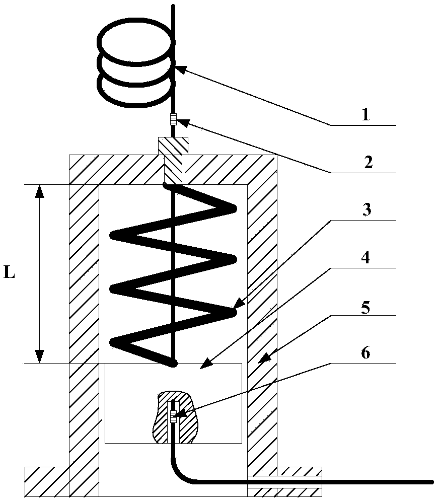
[0028] The structure of the fiber grating geoacoustic sensing probe of the present invention is as follows: figure 1 As shown, it includes an optical fiber 1 , a first chirped grating 2 , a spring 3 , a proof mass 4 , a second chirped grating 6 , and a barrel 5 . The mass block 4 is suspended on the inner wall of the cylinder, and the center top of the cylinder body 5 is provided with an introduction hole. The optical fiber 1 is introduced through the introduction hole of the cylinder body 5, and after passing through the mass block 4, the other end is drawn out from the export hole opened on the support of the cylinder body 5 . One end of the spring 3 is connected to the mass block 4 , and the other end of the spring 3 is connected to the cylinder body 5 ; one end of the optical fiber 1 is cemented to the mass block 4 , and the other end of ...


PUM


Abstract

The invention provides a sensing method of a fiber grating earth sound sensing system. A fiber grating earth sound sensing probe is included, and comprises a fiber, a chirping weak grating, a spring,a mass block, another chirping weak grating and a cylinder; the two ends of the spring are connected with the mass block and the cylinder respectively; and the two ends of the fiber are glued to the mass block and the cylinder respectively. The two chirping gratings including low-reflectivity gratings with the same reflection spectrum, the reflectivity is lower than 1%, and the gratings are arranged beyond a strain sensing area to prevent the grating themselves from strain influence. The invention also discloses a sensing system based on the ground sound sensing probe, and multiple probes canbe multiplexed in a large scale in the system. The sensing probe is simple in structure and high in sensitivity, the time division multiplexing sensing system is constructed based on the probe, the number and sensitivity of a sensor can be configured flexibly according to the concrete application scene, large-scale wide-area sensing monitoring is realized, and the application prospects are good.

Description

technical field [0001] The invention relates to the technical field of sensors, in particular to a sensing method for a fiber grating geoacoustic sensing system. Background technique [0002] Debris flow ground sound means that during the flow of debris flow, the mixed particles will collide with the mountains along the way, generating vibration with a specific frequency. This vibration propagates along the rocks on the ditch bank to generate debris flow ground sound. By monitoring the ground sound of debris flow, early warning can be given to the occurrence of debris flow, so as to maximize the time for disaster prevention and mitigation, and effectively reduce the degree of disaster loss. However, compared with the monitoring of seismic waves, the ground sound intensity generated by debris flow is low, and it decays quickly during the propagation process on the shallow surface. The maximum propagation distance is about 100 meters, and the significant frequency is around 10...

Claims


Application Information

Patent Timeline
Patent Type & Authority Applications(China)
IPC IPC(8): G01H9/00
Inventor 罗志会潘礼庆曾曙光肖焱山陈小刚杨先卫
Owner CHINA THREE GORGES UNIV
Why Eureka
Try Eureka