A clamping device for stress testing

A stress test and clamping device technology, applied in the direction of measuring devices, force/torque/work measuring instruments, force measurement, etc., can solve problems such as too long transmission chain, insufficient rigidity of clamping parts, large repeated positioning errors, etc., to achieve Improved clamping stability and good repeat positioning accuracy

Inactive Publication Date: 2020-11-10
MATERIAL INST OF CHINA ACADEMY OF ENG PHYSICS
View PDF17 Cites 0 Cited by
  • Summary
  • Abstract
  • Description
  • Claims
  • Application Information

AI Technical Summary

Problems solved by technology

The sample platform requires the sample to have a shape plane that can support the sample stably, and it is difficult to realize the positioning control of different areas of the sample to be tested
The claw-type clamping device does not have high requirements on the geometric shape of the sample, but the simple design cannot meet the requirements of precise positioning and position conversion of the sample, while the complex design often faces shortcomings such as insufficient rigidity of the clamping part and too long transmission chain, and is accompanied by Problems such as large repeated positioning errors caused by the accumulation of coordination errors

Method used


Image

  • A clamping device for stress testing
  • A clamping device for stress testing
  • A clamping device for stress testing

Examples


Embodiment 1

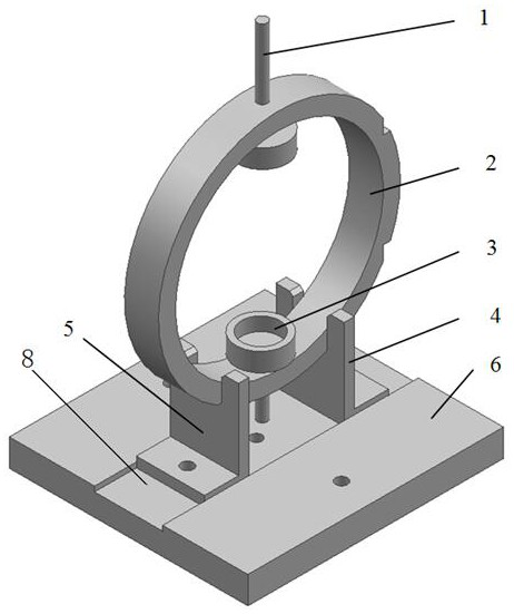
[0039] See figure 1 , figure 2 , image 3 , a stress test clamping device of the present invention, comprising a chuck, a bracket and a base plate; the bottoms of the two brackets are fixed on the base plate by bolts; the upper part of the bracket is provided with a groove; the width of the chuck matches the width of the groove of the bracket The chuck is annular, and at least two pairs of bayonets are formed on the outer circle of the chuck, the center line of each pair of bayonets passes through the center of the chuck circle, and the center lines of the two pairs of bayonets are perpendicular to each other; the position of each pair of bayonets on the chuck Corresponds to the groove of the bracket.

Embodiment 2

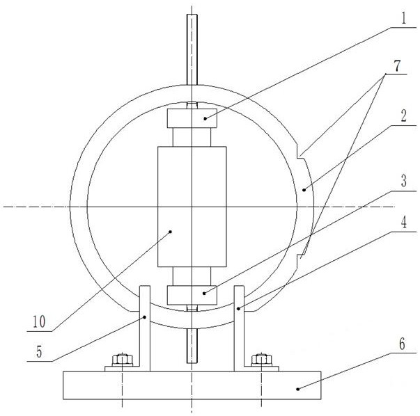
[0041] See figure 1 , figure 2 , image 3, a stress test clamping device of the present invention, comprising a chuck, a bracket and a base plate; the bottoms of the two brackets are fixed on the base plate by bolts; the upper part of the bracket is provided with a groove; the width of the chuck matches the width of the groove of the bracket The chuck is annular, and at least two pairs of bayonets are formed on the outer circle of the chuck, the center line of each pair of bayonets passes through the center of the chuck circle, and the center lines of the two pairs of bayonets are perpendicular to each other; the position of each pair of bayonets on the chuck Corresponding to the groove of the bracket; the chuck is provided with an upper positioning piece and a lower positioning piece, and the upper positioning piece and the lower positioning piece are located on the center line of a pair of bayonet sockets; the upper positioning piece and the lower positioning piece are fix...

Embodiment 3

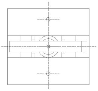
[0043] See figure 1 , figure 2 , image 3 , a stress test clamping device of the present invention, comprising a chuck, a bracket and a base plate; the bottoms of the two brackets are fixed on the base plate by bolts; the upper part of the bracket is provided with a groove; the width of the chuck matches the width of the groove of the bracket The chuck is annular, and at least two pairs of bayonets are formed on the outer circle of the chuck, the center line of each pair of bayonets passes through the center of the chuck circle, and the center lines of the two pairs of bayonets are perpendicular to each other; the position of each pair of bayonets on the chuck Corresponds to the groove of the bracket; the angle of the bayonet is 90°.


PUM

PropertyMeasurementUnit
angleaaaaaaaaaa

Abstract

The invention discloses a multifunctional clamping device for stress test, and belongs to the field of lossless X ray analysis and detection. The device comprises assemblies including an upper positioning piece, a chuck, a lower positioning piece, a support and a base plate, the upper and lower positioning pieces are used for limiting and positioning, the base plate plays a supporting role, and asupport and chuck pair has functions of limiting and supporting. The device can be used in cooperation with sample stages of different types of test instruments, input and output optimal paths of X rays are not shielded during stress test, and the sample clamping stability, the test point switching efficiency, the optical path adaptability and the repeated positioning accuracy are improved in theresidual stress test process via the X ray method due to cooperation of the assemblies in the supporting, limiting and positioning aspects. The device can be used in cooperation with a stress meter toenhance the versatility, and is suitable for stress test of samples in different appearances including cylinder, prism, cuboid, sphere and casing.

Description

technical field [0001] The invention belongs to the field of X-ray non-destructive analysis and detection, and relates to a test auxiliary device, in particular to a multifunctional stress test clamping device. Background technique [0002] After more than a hundred years of development, X-ray diffraction technology has great influence and driving force in many disciplines such as physics, chemistry, materials, biology, and environment. Phase analysis and stress testing based on X-ray crystallography are the most commonly used important analytical testing methods in materials science at the present stage. With the continuous advancement of X-ray technology and the supporting development of the machinery industry, domestic and foreign scientific research instrument development units have introduced a variety of testing instruments. Even if only for a single stress test requirement, various instruments have various appearances and operating platforms due to different test met...

Claims


Application Information

Patent Timeline
Patent Type & Authority Patents(China)
IPC IPC(8): G01L1/25G01L5/00
CPCG01L1/25G01L5/0047
Inventor 王旻窦作勇邓合陈力董鲜峰董平张晨张俊
Owner MATERIAL INST OF CHINA ACADEMY OF ENG PHYSICS
Why Eureka
Try Eureka