Electronic fence control system and method

An electronic fence and control system technology, applied in traffic control systems, traffic control systems, instruments, etc. of road vehicles, can solve problems such as reducing user experience, increasing offline maintenance costs, judging lag and unfavorable vehicle control, etc., to achieve Effects of prolonging service life, reducing operating costs, and improving accuracy

Active Publication Date: 2018-11-27
武汉小象创意科技有限公司
View PDF5 Cites 15 Cited by
  • Summary
  • Abstract
  • Description
  • Claims
  • Application Information

AI Technical Summary

Problems solved by technology

[0007] Although the above-mentioned patent document discloses an electronic fence control method based on dockless vehicles, the electronic fence control method disclosed in this patent document requires repeated communication between intelligent hardware and the back-end server, and the judgment hysteresis caused by communication delay is not conducive to vehicle control. , thus increasing offline maintenance costs and reducing user experience

Method used


Image

  • Electronic fence control system and method
  • Electronic fence control system and method
  • Electronic fence control system and method

Examples


Embodiment 1

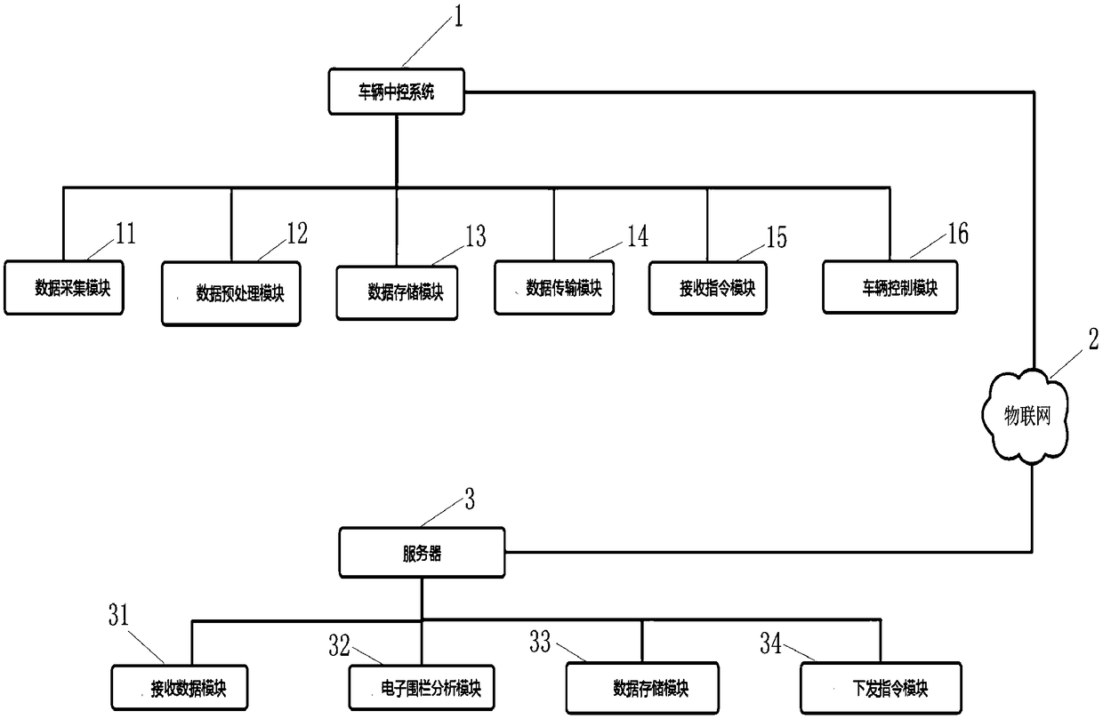
[0040] see figure 1 , the electronic fence control system includes a vehicle central control system 1 and a server 3, the vehicle central control system 1 includes a data acquisition module 11 and a vehicle control module 16, and the data acquisition module 11 is used to pass the vehicle GPS locator Collect current vehicle information and location latitude and longitude data; it can also collect vehicle travel time, speed, phase angle and other information;

[0041] The vehicle control module 16 is used to control the opening or closing of the vehicle; for example: to control the vehicle to open the electric door command, the vehicle control module 16 opens the vehicle electric door through the central control system 1; the vehicle closes the electric door command, the vehicle control Module 16 closes the vehicle electric door through the central control system 1; locks the rear wheel lock command of the vehicle, locks the rear wheel lock of the vehicle through the vehicle cen...

Embodiment 2

[0049] see figure 1 The difference from the above-mentioned embodiment is that the service 3 includes an instruction module 34 for controlling the vehicle to leave the electronic fence control area after analyzing and processing the vehicle information by the server 3 .

[0050] Preferably, the server 3 further includes a data storage module 33, which is used for the server 3 to receive vehicle information.

Embodiment 3

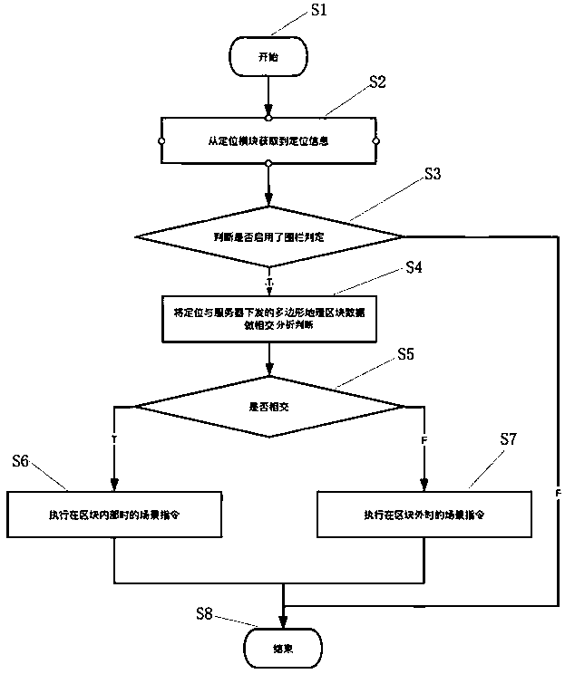
[0052] see figure 2 , the difference from the above-mentioned embodiments is that a method for controlling an electronic fence, the method includes the following steps:

[0053] Step 1), start S1;

[0054] Step 2), obtaining vehicle positioning information S2 from the vehicle central control system;

[0055] Step 3), judging whether the electronic fence analysis module 32 is enabled to determine the vehicle operating range S3;

[0056] Step 4), according to the obtained vehicle location information and the polygonal data intersection analysis of electronic fence buffer splitting, judge the vehicle position information S4;

[0057] Step 5), if the vehicle positioning information intersects with the polygonal area data split by the electronic fence buffer zone, then enter the next step S5;

[0058] Step 6), execute the scene instruction S6 in the electronic fence control block;

[0059] Step 7), end S8.

[0060] The above-mentioned step 3) the vehicle positioning informati...


PUM


Abstract

The invention discloses an electronic fence control system and method. The system comprises a vehicle central control system and a server, wherein the vehicle central control system comprises a datacollection module and a vehicle control module; the server comprises a data receiving module and an electronic fence analysis module. The vehicle information and the vehicle control information collected by the vehicle central control system are transmitted to the server through Internet of things; the server analyzes and processes the received information to control the vehicle operation. The method comprises the following steps of 1, obtaining vehicle positioning information; 2, judging whether the electronic fence analysis module is started to be used or not; 3, analyzing and judging the vehicle position information according to the intersection of the obtained vehicle positioning information and the electronic fence dismounting polygonal region data; 4, judging whether the vehicle positioning information and the electronic fence dismounting polygonal region data are intersected or not; 5, executing a scene instruction in an electronic fence control region block. The invention provides the electronic fence control system and method with the advantages that the electronic fence data processing speed is higher; the vehicle operation control is more precise.

Description

technical field [0001] The invention relates to the technical field of vehicle management and control, in particular to an electronic fence control system and method. Background technique [0002] Geographic location-based scene control is an especially common part of modern IoT applications. Under normal circumstances, we need IoT devices to send several copies of electronic fence data. The IoT devices, for example: shared electric bicycles; during the movement of the shared electric bicycles, after obtaining the geographical location through the built-in positioning chip, and Compare the electronic fence stored locally to achieve the purpose of intelligent control. [0003] In the usage scenario of shared motorcycles, the vehicle needs to be within the operating range to be able to drive normally. The system will issue an electronic fence within the operating range to the vehicle. Once it crosses the electronic fence, it will automatically close the switch to prevent the ...

Claims


Application Information

Patent Timeline
Patent Type & Authority Applications(China)
IPC IPC(8): G08G1/00
CPCG08G1/205
Inventor 高健李纪飞
Owner 武汉小象创意科技有限公司
Why Eureka
Try Eureka