
Inverter upper bridge driving circuit

A bridge drive circuit and inverter technology, applied in the power supply field, can solve the problems of high cost and large volume, and achieve the effect of simple circuit and high reliability

Inactive Publication Date: 2018-11-27
GUANGDONG BESTEK E COMMERCE CO LTD
View PDF4 Cites 5 Cited by
  • Summary
  • Abstract
  • Description
  • Claims
  • Application Information

AI Technical Summary

Problems solved by technology

The use of optocoupler isolation drive or transformer isolation drive circuit has high cost and large volume

Method used


Image

  • Inverter upper bridge driving circuit
  • Inverter upper bridge driving circuit
  • Inverter upper bridge driving circuit

Examples


Embodiment Construction

[0023] In order to enable those skilled in the art to better understand the solutions of the present invention, the technical solutions in the embodiments of the present invention will be clearly and completely described below in conjunction with the drawings in the embodiments of the present invention. Unless otherwise defined, all technical and scientific terms used herein have the same meaning as commonly understood by one of ordinary skill in the technical field of the invention. The terms used herein in the description of the present invention are for the purpose of describing specific embodiments only, and are not intended to limit the present invention.

[0024] Reference herein to an "embodiment" means that a particular feature, structure, or characteristic described in connection with the embodiment can be included in at least one embodiment of the present invention. The occurrences of this phrase in various places in the specification are not necessarily all referrin...


PUM


Abstract

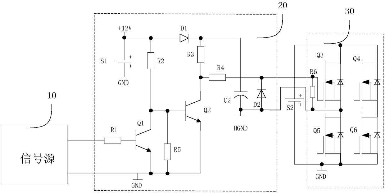
The invention discloses an inverter upper bridge driving circuit. The inverter upper bridge driving circuit comprises a charging circuit and a driving circuit, wherein the charging circuit comprises afirst diode D1 and a first capacitor C2, the charging circuit is used for charging the first capacitor C2 through first power supplying voltage to provide second power supplying voltage through the first capacitor C2; the driving circuit comprises a first transistor Q2, a collector electrode of the first transistor Q2 is connected with a controlled end of an upper bridge transistor Q3 of a bridge-type inverter circuit, and the driving circuit is used for driving break-over or cut-off of the upper bridge transistor Q3 of the bridge-type inverter circuit through the second power supplying voltage output by the first capacitor C2. The inverter upper bridge driving circuit is simple, high in reliability, low in overall power and low in production cost; meanwhile, shoot-through of the upper bridge transistor Q3 and a lower bridge transistor Q5 can be avoided.

Description

technical field [0001] The invention relates to the technical field of power supplies, in particular to an inverter upper bridge drive circuit. Background technique [0002] The N-type switching tube or bridge circuit commonly used in power electronics is used as an electronic switch. The switching tube works in the switching mode, the source (or emitter) of the lower tube is connected to the power supply ground, and the gate level is relative to the source (or emitter) changes, but the magnitude is small. The drain (or collector) of the upper tube is positively connected to the power supply, and the potential of the drain (or collector) is constant during operation, while the source (or emitter) of the upper tube is in a negative (or positive) position from the ground to the positive of the power supply relative to the power supply. Or the power supply is in the high-speed jump to the ground. The above working characteristics determine that the upper tube drive is the dif...

Claims


Application Information

Patent Timeline
IPC IPC(8): H02M1/08H02M1/38
CPCH02M1/08H02M1/38
Inventor 徐新华唐锋
Owner GUANGDONG BESTEK E COMMERCE CO LTD
Learn More