
Interventional valve assembly, interventional valve fixing device and application thereof

A technology of fixing devices and components, which is applied in the field of medical devices, can solve problems such as low annulus friction coefficient, difficulty in improving friction coefficient, and affecting valve performance, etc., and achieve a narrow solution range

Inactive Publication Date: 2018-11-30
KINGSTRONBIOCHANGSHU CO LTD
View PDF9 Cites 1 Cited by
  • Summary
  • Abstract
  • Description
  • Claims
  • Application Information

AI Technical Summary

Problems solved by technology

[0003] At present, the fixation between the interventional valve and the valve annulus mainly acts on the valve annulus through the radial force formed by the compression of the valve frame, and then the interventional valve is positioned on the implantation site through the friction force between the valve annulus and the valve. , the friction between the valve annulus and the interventional valve is one of the most important factors to determine whether the interventional valve can be placed reliably and stably at the implantation site, and the frictional force depends on two factors, one is the size of the valve holder after implantation Radial force, the other is the friction coefficient between the valve and the valve ring, as shown in the formula: F=μ×Fn, wherein F is the friction force between the valve and the valve ring, μ is the friction coefficient between the valve and the valve ring, Fn is the radial force caused by the compression of the valve frame. If the friction force F is less than the blood pressure between the valves, the valve will not be fixed, and the valve will slide away from the correct fixed position, which will eventually lead to the failure of the operation. Therefore, the friction force F must greater than the blood pressure between the valves, and the change of the friction force needs to be changed from the friction coefficient and the radial force Fn. Among them, the friction coefficient μ is mainly related to the material and structure of the contact part with the valve annulus and the state of the human valve annulus. The limitation of selection makes it difficult to increase the coefficient of friction from the perspective of the valve; while increasing the coefficient of friction from the perspective of the valve annulus is beyond human control, because when the valve leaflets are calcified, the friction coefficient of the valve annulus becomes large, The annulus friction coefficient of non-calcified patients is low, which narrows the range of indications for interventional valves, and the radial force Fn mainly determines the rigidity of the valve frame and the radial compression of the valve, and excessive compression of the valve will affect The performance of the valve, so the rigidity of the valve frame can only be improved to improve the radial force of the valve
[0004] However, due to the increase of the radial force of the valve, the operation of the delivery system will be more difficult, and more importantly, it will also cause fatal dangers such as blockage of the coronary ostium.

Method used


Image

  • Interventional valve assembly, interventional valve fixing device and application thereof
  • Interventional valve assembly, interventional valve fixing device and application thereof
  • Interventional valve assembly, interventional valve fixing device and application thereof

Examples


Embodiment 1

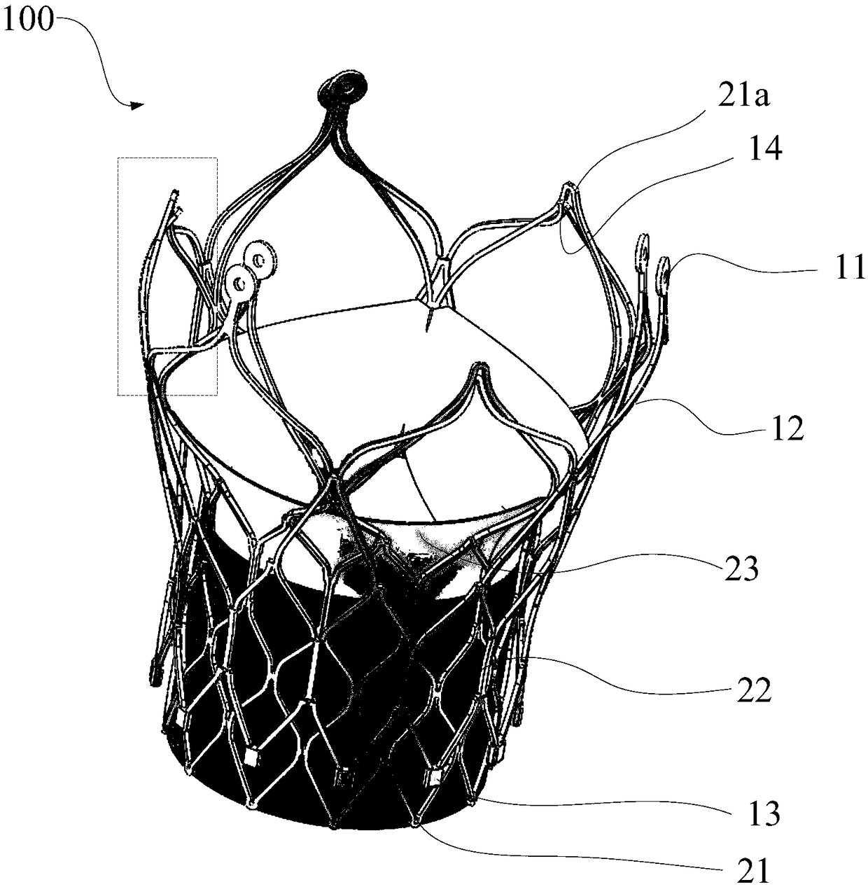
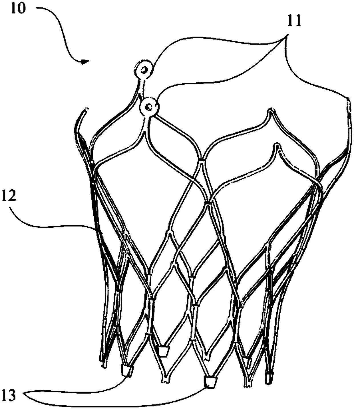
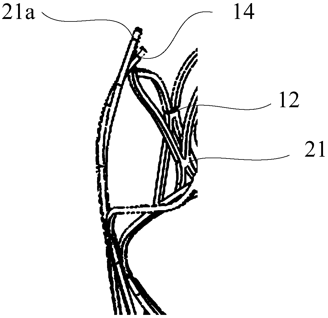
[0048] figure 1 It is a schematic diagram of the assembly structure of the interventional valve and the interventional valve fixing device in the interventional valve assembly provided by Embodiment 1 of the present invention, figure 2 It is a schematic structural diagram of the interventional valve fixing device in the interventional valve assembly provided by Embodiment 1 of the present invention, image 3 for figure 1 The enlarged schematic diagram of the dotted box in the middle.

[0049] This embodiment provides an interventional valve assembly 100, refer to Figure 1-2 As shown, the interventional valve assembly 100 includes: an interventional valve and a radially shrinkable interventional valve fixing device 10 for fixing the interventional valve in the annulus, that is, in this embodiment, the interventional valve fixing device 10 is radially shrinkable , and the interventional valve is fixed in the valve annulus by the interventional valve fixing device 10, wherei...

Embodiment 2

[0063] This embodiment provides an interventional valve fixation device 10, wherein the interventional valve fixation device 10 fixes the interventional valve implanted in the body in the annulus, such as figure 2 As shown, the interventional valve fixing device 10 at least includes: a radially expandable fixing frame 12, specifically, the fixing frame 12 is an elastic body, which can shrink and expand radially, and at the same time, as figure 2 As shown, the fixed frame 12 is a revolving body composed of a hollowed-out mesh structure. It should be noted that the fixed frame 12 can also be a hollowed-out mesh structure, but is not limited to being a revolving body, and can also be other mesh structures, wherein , in this embodiment, when the interventional valve fixing device 10 is delivered, the fixing frame 12 is shrunk into the delivery system, and after being implanted in the human body, the fixing frame 12 expands radially, specifically, the fixing frame 12 is fixed abov...

Embodiment 3

[0074] Figure 4 It is a schematic diagram of the application of the interventional valve fixation device provided by the present invention in the aortic valve.

[0075] This embodiment provides an application of the interventional valve fixing device 10 described in any of the above embodiments in the aortic valve, that is, in this embodiment, the interventional valve fixing device 10 is applied in the interventional operation of the aortic valve, Specifically, when the interventional valve is implanted in the annulus of the aortic valve, in order to fix the interventional valve in the annulus of the aortic valve, in this embodiment, the interventional valve fixing device 10 is used to fix the interventional valve, that is, this embodiment In an example, the interventional valve fixing device 10 is used to fix the interventional valve implanted in the aortic valve, specifically, as Figure 4As shown, the aortic valve is located between the left ventricle 40 and the aorta 30,...


PUM


Abstract

The invention provides an interventional valve assembly, an interventional valve fixing device and an application thereof. The interventional valve assembly comprises an interventional valve and the interventional valve fixing device for fixing the interventional valve in an annulus and capable of contracting in the radial direction, wherein the interventional valve fixing device is fixed above the annulus, and one end of the interventional valve fixing device abuts against the top end of the annulus. One part of the interventional valve is located in the annulus, and the other part extends out of the annulus to abut against the inner wall of the interventional valve fixing device to fix the interventional valve in the annulus through the interventional valve fixing device. The interventional valve assembly solves the problem in the prior art that the interventional valve conveying difficulty is increased and coronary artery occlusion risk is increased due to the fact that the interventional valve is fixed by increasing the radial force of the interventional valve, and solves the problem that the existing interventional valve is narrow in indication range.

Description

technical field [0001] The invention relates to the technical field of medical devices, in particular to an interventional valve assembly, an interventional valve fixing device and applications thereof. Background technique [0002] Artificial heart valves are divided into mechanical valves, biological valves, and transcatheter implanted artificial heart valves (ie, interventional valves). The interventional valve is mainly composed of a valve frame, leaflets and valve skirt. The implantation process of the interventional valve is as follows: first The interventional valve is compressed into a set of transcatheter delivery system, and then the delivery system is used to deliver the interventional valve to the implantation site through the blood vessel or the apex of the heart and release it, and fix it in the annulus. [0003] At present, the fixation between the interventional valve and the valve annulus mainly acts on the valve annulus through the radial force formed by th...

Claims


Application Information

Patent Timeline
Patent Type & Authority Applications(China)
IPC IPC(8): A61F2/24
CPCA61F2/24A61F2/2418
Inventor 钟生平靳永富孟春旺张波
Owner KINGSTRONBIOCHANGSHU CO LTD
Learn More