Metal part grafting printing method

A technology of metal parts and software, applied in the field of 3D printing, can solve the problems of affecting production work, long time, high cost, etc., and achieve the effect of reducing cost and production efficiency, broadening the application field and improving efficiency

Active Publication Date: 2018-11-30
GUANGDONG INST OF NEW MATERIALS
View PDF7 Cites 11 Cited by
  • Summary
  • Abstract
  • Description
  • Claims
  • Application Information

AI Technical Summary

Problems solved by technology

However, this technology requires a laser to completely melt each layer of powder and has high requirements for the dimensional accuracy of the final formed part. The layer thickness during printing is generally set to 20um-40um for high precision and 40um-80um for low precision, so there are also some problems. : 1. It takes a long time for large models, especially for relatively high models, to be directly selected for laser melting
Moreover, if the equipment works uninterruptedly for a long time, ...

Method used


Image

  • Metal part grafting printing method
  • Metal part grafting printing method
  • Metal part grafting printing method

Examples


Embodiment 1

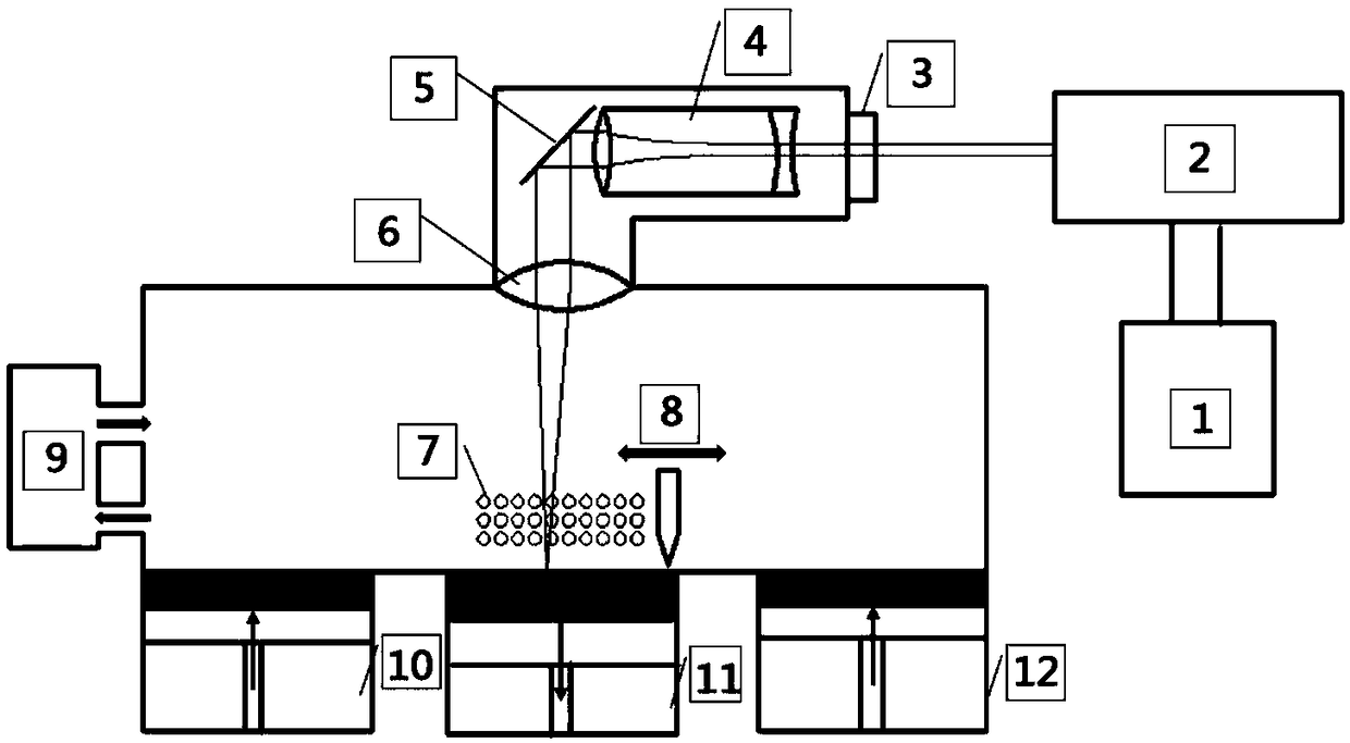
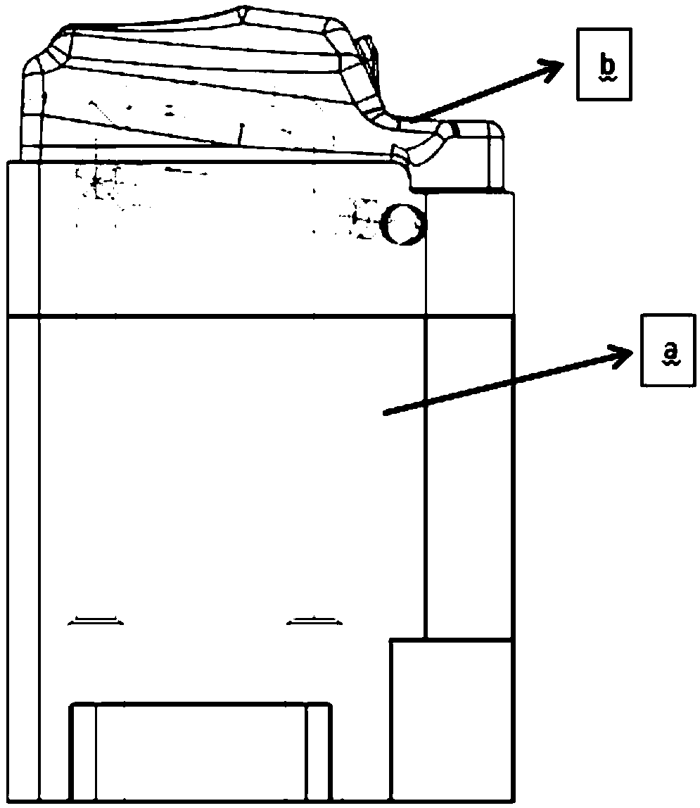
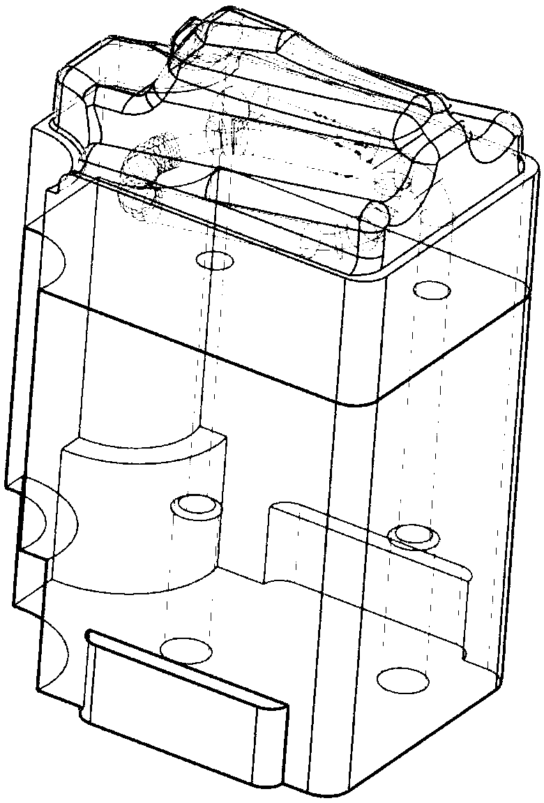
[0051] figure 1 Schematic diagram of the selective laser melting equipment provided for the embodiment of the present invention; figure 2 The front view of the model to be produced for the embodiment of the present invention (wherein a is the part to be machined, and b is the part to be manufactured by selective laser melting); image 3 An isometric side view of a model to be produced for an embodiment of the invention; Figure 4 Bottom view of the machined portion of the model to be produced for an embodiment of the invention; Figure 5 Top view of the desired machined portion of the model to be produced for an embodiment of the invention Figure 6 The top view of the laser sintering path of the desired machined part of the model to be produced for the embodiment of the present invention, wherein (1 is the path of laser sintering for the first time; 2 is the path of laser sintering for the second time; 3 is the path of laser sintering for the first time tertiary sintering...


PUM


Abstract

The invention discloses a metal part grafting printing method. The method comprises the following steps that CAD software is utilized to plan an area to be machined and an area to be subjected to selective laser melting machining on product production models, after a machining model adopts a traditional method to machine a finished product, a special method is adopted to carry out accurate positioning on the upper surface of the finished product and the area to be subjected to selective laser melting, and then grafting printing forming is carried out. The method belongs to composite manufacturing, the metal part grafting printing method based on the selective laser melting technology can fully play the advantages of 3D printing, the printing cost of a large-scale part including a part of complex structures is greatly reduced while the production efficiency is greatly improved, the cost can be reduced to be 30% or below of the original printing cost to the maximum, and the efficiency can be improved by 70% or above to the maximum; and the method is suitable for grafting and printing of any metal powder capable of being printed, so that the application field of metal 3D printing is expanded.

Description

technical field [0001] The invention relates to the technical field of 3D printing, and in particular to a method for grafting and printing metal parts. Background technique [0002] Today's industrial production market is undergoing tremendous changes all the time. On the one hand, consumer demand is becoming more personalized and diversified; on the other hand, product manufacturers are all focusing on the fierce competition in the global market. Faced with such a rapidly changing and unpredictable buyer's market, manufacturers must not only quickly design products that meet people's consumption needs, but also produce them quickly in order to seize the market. In addition, with the development of computer technology, the functions of modeling software are becoming more and more perfect and diversified, so that designers can design more complex, diverse and even arbitrary works. [0003] However, the traditional mass production mode responds slowly to the market and canno...

Claims


Application Information

Patent Timeline
IPC IPC(8): B22F3/105B22F5/00B33Y10/00B33Y50/00
CPCB22F3/105B22F5/00B33Y10/00B33Y50/00
Inventor 董东东马文有刘敏王昊王岳亮赵国瑞
Owner GUANGDONG INST OF NEW MATERIALS
Why Eureka
Try Eureka