
Numerically-controlled double working position cutting machine and control method thereof

A control method and cutting machine technology, which are applied in metal processing machinery parts, manufacturing tools, metal sawing equipment, etc., can solve the problems of reducing processing efficiency and increasing the number of workpiece turnover, so as to improve processing efficiency and reduce equipment footprint. , the effect of low manufacturing cost

Pending Publication Date: 2018-11-30
谭明
View PDF0 Cites 4 Cited by
  • Summary
  • Abstract
  • Description
  • Claims
  • Application Information

AI Technical Summary

Problems solved by technology

[0002] The workpiece is generally bent by a CNC bending machine to meet the requirements of the bending angle. In order to meet the end face size and end face quality of the bent workpiece, further cutting processing is required. Most of the existing cutting machines use the process of cutting both ends of the workpiece in sequence. , every time the cutting process of one end is completed, the workpiece often needs to be re-clamped, which increases the turnover times of the workpiece and reduces the processing efficiency

Method used


Image

  • Numerically-controlled double working position cutting machine and control method thereof
  • Numerically-controlled double working position cutting machine and control method thereof
  • Numerically-controlled double working position cutting machine and control method thereof

Examples


Embodiment Construction

[0029] The present invention will be described in further detail below in conjunction with the accompanying drawings.

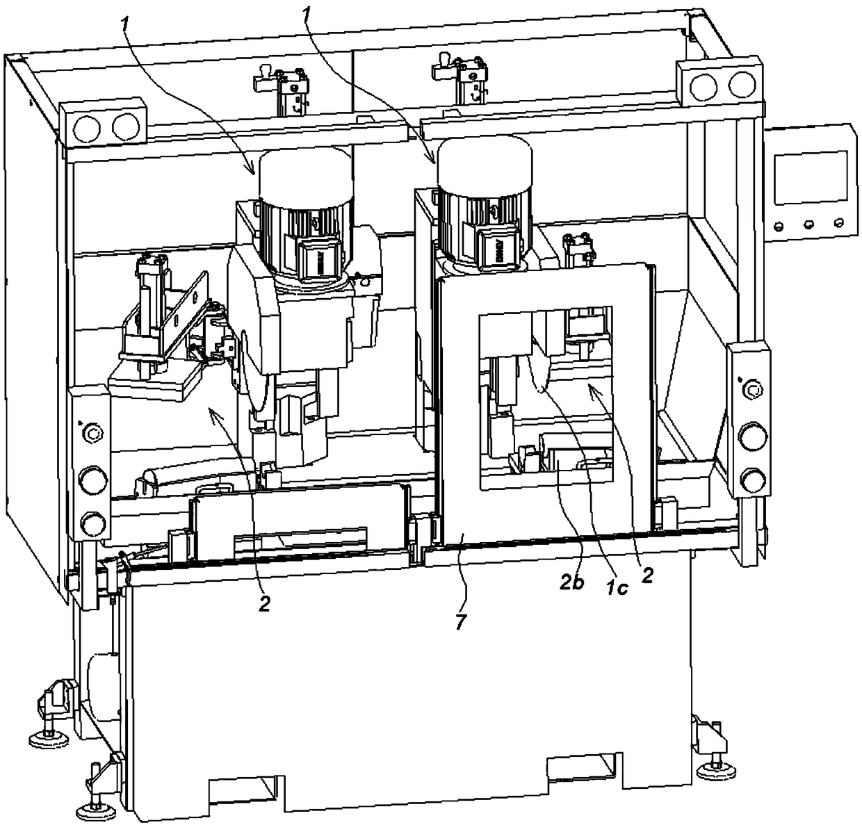
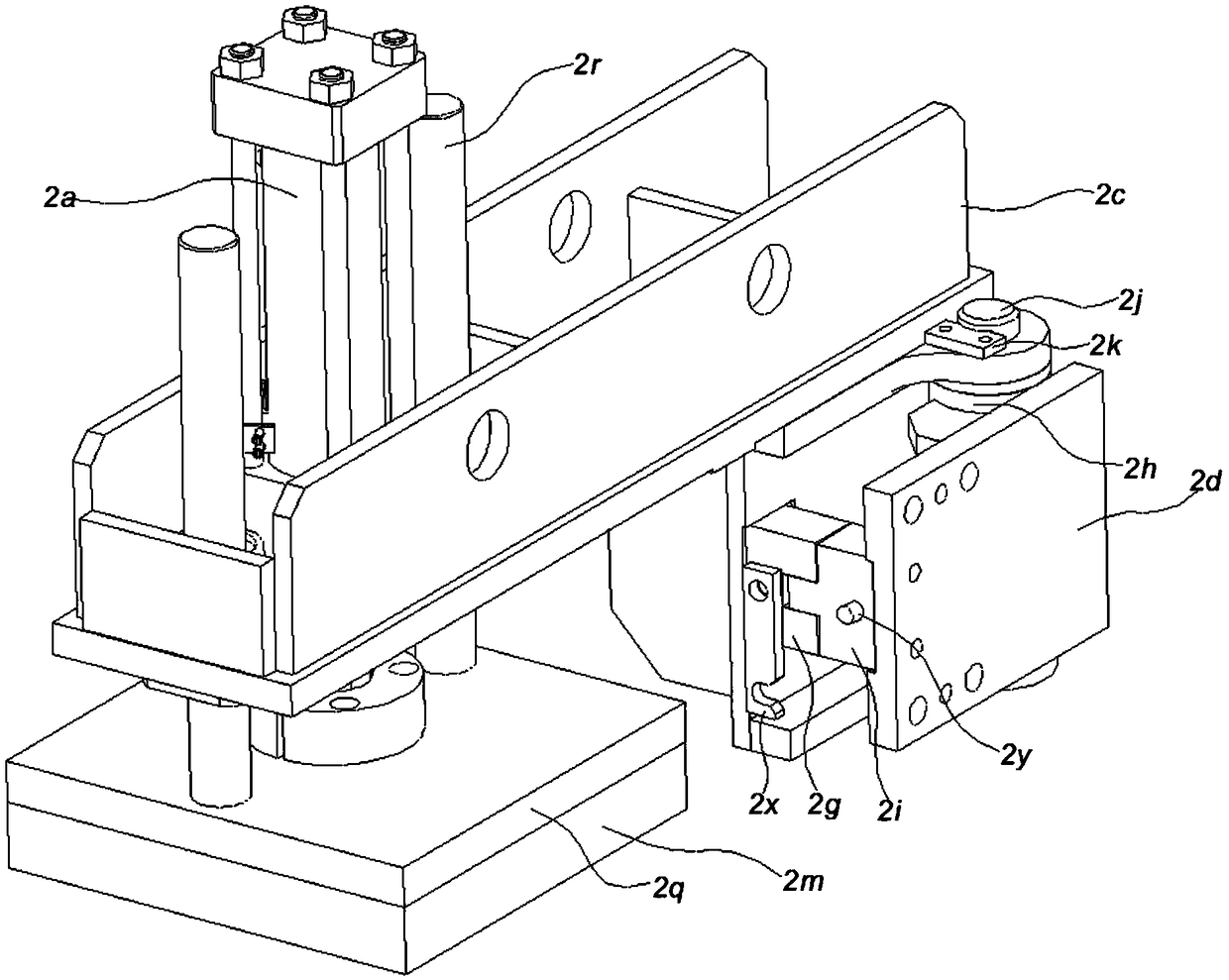
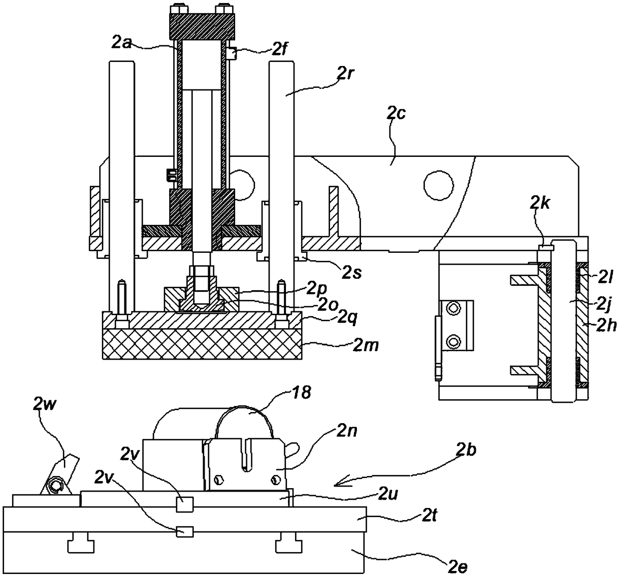
[0030] Such as figure 1 , 4 As shown, the CNC double-station cutting machine includes a cutting mechanism 1, a clamping mechanism 2, a cutting fluid container 3, a nozzle 4, a spiral magnetic separator 5, a chip collecting container 6, a safety door 7, a safety grating 8 and a PLC9. The cutting mechanism 1 is matched with the clamping mechanism 2 .

[0031] The nozzle 4 is connected to the cutting fluid container 3 through the flow regulating valve 10 and the cutting fluid pump 11 in turn. The nozzle 4 is installed facing the saw blade 1c, and the spiral magnetic separator 5 is installed under the saw blade 1c. The spiral magnetic separator 5 is produced by Taizhou Ruichuang. The model is CF-200 spiral magnetic separator. A chip collection container 6 is installed below the spiral magnetic separator 5 , and the cutting fluid container 3 communicates with t...


PUM


Abstract

The invention discloses a numerically-controlled double working position cutting machine. The numerically-controlled double working position cutting machine includes two cutting mechanisms and two clamp mechanisms; each cutting mechanism includes a feeding oil cylinder, a motor and a saw blade, the saw blades are mounted on the motors, and the motors are mounted on the feeding oil cylinders; eachclamp mechanism includes a clamp oil cylinder and a workpiece copying mold, the workpiece copying molds are mounted on the clamp oil cylinders, and the cutting mechanisms and the clamp mechanisms arecooperatively mounted. The invention further discloses a control method of the numerically-controlled double working position cutting machine. The control method includes the steps that a PLC receivesposition signals of a position feedback sensor and conducts judging; when a feeding position is close to the 1 / 3 position of the upper portion of a workpiece, the PLC controls the opening degree of aservo proportioning valve to increase, and the workpiece is fed and subjected to acceleration cutting; when the feeding position is close to the 1 / 3 position of the lower portion of the workpiece, the PLC controls the opening degree of a servo proportioning valve to reduce, and the workpiece is fed and subjected to reduction cutting. By adopting the numerically-controlled double working positioncutting machine and the control method thereof, the number of turnover times of the machined workpiece is reduced, and the machining efficiency is high; the numerically-controlled double working position cutting machine is small in occupied space, low in manufacturing cost, high in machining control accuracy and safety performance and convenient to maintain.

Description

technical field [0001] The invention belongs to the field of cutting machines, and in particular relates to a cutting machine for synchronously cutting both ends of a workpiece and an electric automatic control method. Background technique [0002] The workpiece is generally bent by a CNC bending machine to meet the requirements of the bending angle. In order to meet the end face size and end face quality of the bent workpiece, further cutting processing is required. Most of the existing cutting machines use the process of cutting both ends of the workpiece in sequence. , Every time the cutting process of one end is completed, the workpiece often needs to be re-clamped, which increases the turnover times of the workpiece and reduces the processing efficiency. Contents of the invention [0003] The purpose of the present invention is to provide a numerically controlled double-station cutting machine, which can reduce the turnover, reduce the floor space of the equipment, th...

Claims


Application Information

Patent Timeline
Patent Type & Authority Applications(China)
IPC IPC(8): B23D45/02B23D45/10B23D47/04B23D47/02B23D59/00B23Q11/08B23Q11/10
CPCB23D45/021B23D45/10B23D47/02B23D47/04B23D59/001B23D59/006B23Q11/0891B23Q11/1069B23Q11/1076
Inventor 谭明
Owner 谭明
Learn More