
Optical direct current measuring device for direct current high-voltage transmission

A high-voltage direct current transmission and direct current technology, applied in measuring devices, only measuring current, measuring electrical variables, etc., can solve the problems of harsh working environment, easy damage, and easy burnout and failure of laser emitting devices, and reach the fluctuation range. Large, long life, avoid the effect of uneven high voltage electric field

Active Publication Date: 2018-11-30
BEIJING SIFANG JIBAO AUTOMATION
View PDF12 Cites 2 Cited by
  • Summary
  • Abstract
  • Description
  • Claims
  • Application Information

AI Technical Summary

Problems solved by technology

The working environment of the analog-to-digital conversion device containing electronic components is usually harsh at the high-voltage end, and it is easy to be damaged
The high-voltage photocell of the laser energy supply circuit, the optical fiber circuit for laser energy supply, and the laser emitting device are prone to burnout and failure over time

Method used


Image

  • Optical direct current measuring device for direct current high-voltage transmission
  • Optical direct current measuring device for direct current high-voltage transmission
  • Optical direct current measuring device for direct current high-voltage transmission

Examples


Embodiment Construction

[0040] The technical solution of the present invention will be further introduced in detail below in conjunction with the accompanying drawings of the description.

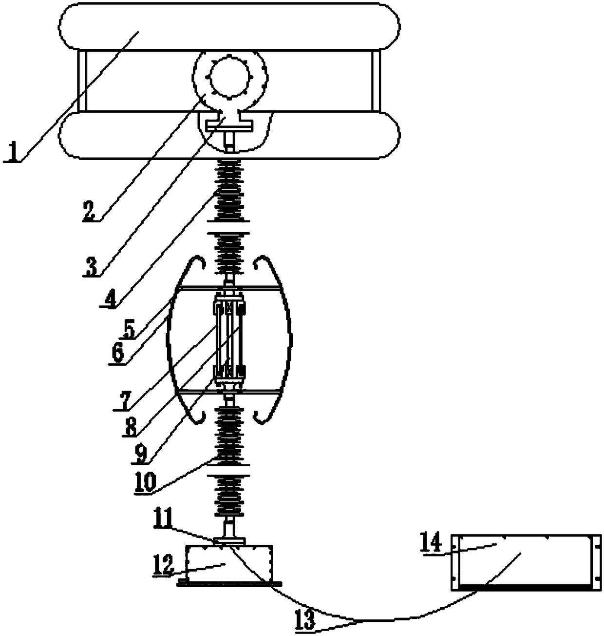
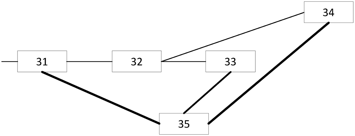
[0041] figure 1 Schematic diagram of the optical DC current measurement device for HVDC transmission, figure 2 It is the schematic diagram of the sensing circuit of the 800kV flexible DC current measuring device, image 3 It is the composition diagram of the high-speed modulation and demodulation unit of the 800kV flexible DC current measuring device, Figure 4 It is the working flow diagram of the 800kV flexible DC current measuring device.

[0042] The invention discloses an optical direct current measuring device for high-voltage direct current transmission, which comprises a sensing optical fiber ring body 2, an upper flange structure 3, an upper equalizing ring 1, an upper high-voltage polarization-maintaining optical fiber insulator 4, and a middle equalizing ring 6 , the middle pressure equalizing ring ...


PUM


Abstract

The invention discloses an optical direct current measuring device for direct current high-voltage transmission. The high-voltage primary end adopts an all-fiber sensing mode, the primary end and thesecondary end adopt a polarized light transmission scheme of segmentally folded silicone rubber insulator pre-embedded polarization-maintaining fiber, and the secondary end adopts a high-speed opticalmodulation and demodulation scheme to realize the direct current measurement. A sensing optical fiber ring loop body and an upper flange structure are located at the top of an upper high voltage polarization-maintaining fiber insulator, an upper equalizing ring in located on the outer periphery of a sensing optical fiber ring body, a middle equalizing ring is located at the junction of insulatorsat both ends, a lower flange structure and a lower fiber storing box body are located at the bottom of the insulators, a high-speed demodulation unit is located on the secondary side. The optical direct current measuring device is suitable for current measurement of a high-voltage direct current, especially an extra-high voltage flexible direct current polarity bus direct current, and the performance of a control protection system is improved.

Description

technical field [0001] The invention belongs to the technical field of electrical measurement, and relates to a current measuring device for a high-voltage direct current transmission line, in particular to a direct current measuring device for a polar bus of a high-voltage flexible direct current transmission. Background technique [0002] High-voltage direct current transmission, especially high-voltage flexible direct current transmission technology is an important means to form the backbone grid of the energy Internet and clean energy grid-connected interconnection in the future. It has the characteristics of high wave content and large current fluctuation. The control and protection system needs to quickly implement control strategies and protection actions based on the current measurement results on the high-voltage polar bus. The faster and more accurately the current measurement device can measure the current on the bus, the more beneficial it is for the stability an...

Claims


Application Information

Patent Timeline
Patent Type & Authority Applications(China)
IPC IPC(8): G01R19/00
CPCG01R19/0092
Inventor 刘海锋张超孟祥强李秦叶艳军秦红霞
Owner BEIJING SIFANG JIBAO AUTOMATION
Learn More