
Cardiology disease examination and treatment device

A treatment device, a technique of cardiology, applied in the direction of medical automatic diagnosis, computer-aided medical procedure, medical informatics, etc., can solve the problems of low accuracy of measurement results and so on

Pending Publication Date: 2018-11-30
郭敏
View PDF0 Cites 0 Cited by
  • Summary
  • Abstract
  • Description
  • Claims
  • Application Information

AI Technical Summary

Problems solved by technology

[0007] The existing phase noise measurement methods all use special hardware circuits to extract the phase information of the signal source under test, and use this to analyze the SSB phase noise of the signal source under test, so that the extraction performance of the phase extraction circuit is largely Determines the performance of the phase noise measurement, and the frequency response of the phase extraction circuit will also affect the measurement results
[0008] The existing phase noise measurement method uses the frequency response of the phase extraction circuit, which has the problem of low accuracy of the measurement results

Method used


Image

  • Cardiology disease examination and treatment device
  • Cardiology disease examination and treatment device
  • Cardiology disease examination and treatment device

Examples


Embodiment 1

[0133] In the present embodiment, the carrier frequency of the measured signal is 600MHz, and the power spectrum of the measured signal is measured with a spectrum analyzer AV4036F, and the phase noise of the measured signal is calculated according to the method of the present invention using the power spectrum data measured, and the phase noise is given measurement results. And the phase noise measurement result of the algorithm of the present invention is compared with the direct measurement result of the phase noise measurement module of AV4036F to illustrate the implementation process and effectiveness of the method of the present invention.

[0134] Figure 4 The power spectrum curve of the measured signal measured by the spectrum analyzer AV4036F and the fitting result of the nonlinear least squares method are given using the measured data of the power spectrum. The phase noise coefficient of the measured signal obtained from the fitting result is:

[0135]

[0136]...

Embodiment 2

[0144] In the embodiment, the carrier frequency of the signal to be tested is 800MHz. The spectrum analyzer AV4036F is used to measure the power spectrum of the measured signal, and the measured power spectrum data is used to calculate the phase noise of the measured signal according to the method of the present invention, and the measurement result of the phase noise is given. And the phase noise measurement result of the algorithm of the present invention is compared with the direct measurement result of the phase noise measurement module of AV4036F to illustrate the implementation process and effectiveness of the method of the present invention.

[0145] Image 6 The power spectrum curve of the measured signal measured by the spectrum analyzer AV4036F and the fitting result of the nonlinear least squares method are given using the measured data of the power spectrum. The phase noise coefficient of the measured signal obtained from the fitting result is:

[0146]

[014...


PUM


Abstract

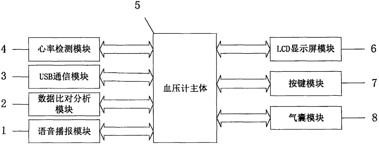
The invention belongs to the technical field of medical equipment, and discloses a cardiology disease examination and treatment device. The cardiology disease examination and treatment device comprises a voice broadcast module, a data analysis and comparison module, a USB communication module, a heart rate detection module, a sphygmomanometer body, an LCD display screen module, a button module, and an air bag module. The invention breaks the problem that detection data of the traditional cardiology examination devices is single. When the data is detected, the data can be analyzed and comparedwith data in a database, the cardiology disease examination and treatment device can display and voice-broadcast the data to the patient, tells the patient that the heart has problems in certain directions, can give the patient some general and effective treatment and maintenance plans before the patient goes to a doctor, and informs the patient of the appropriate medical treatment so as to prevent the patient from missing the best treatment opportunity.

Description

technical field [0001] The invention belongs to the technical field of medical equipment, in particular to a device for examining and treating diseases in the department of cardiology. Background technique [0002] At present, the existing technologies commonly used in the industry are as follows: [0003] The Department of Cardiology, that is, the Department of Cardiology, is also the most common clinical department in our hospital. Common cardiology diseases include angina pectoris, hypertension, coronary heart disease, heart disease, arrhythmia, myocarditis and a series of diseases. Diagnosis and treatment are especially important for patients with cardiology diseases. At present, traditional cardiology disease detection devices can only detect some of the most routine data such as blood pressure and heart rate of patients. Often, some patients do not pay attention to their own conditions due to lack of professional medical knowledge after the detection, and miss the be...

Claims


Application Information

Patent Timeline
IPC IPC(8): G16H50/20
CPCG16H50/20
Inventor 郭敏王才阳李峰花
Owner 郭敏
Learn More