Surface grinding device for wafer producing and processing

A surface grinding and wafer technology, applied in the direction of grinding devices, grinding machine tools, metal processing equipment, etc., can solve the problems of damage, poor adaptability, poor reliability, etc., to improve the clamping effect, ease the clamping hardness, and improve the adaptability effect of ability

Pending Publication Date: 2018-11-30
江苏英锐半导体有限公司
View PDF0 Cites 10 Cited by
  • Summary
  • Abstract
  • Description
  • Claims
  • Application Information

AI Technical Summary

Problems solved by technology

[0002] As we all know, the surface grinding device used for wafer production and processing is a kind of grinding of the knife marks and concave-convex surfaces caused by slicing on the surface of the wafer slices after slicing, so as to better regulate the thickness of the wafer slices and reduce the gap between slices and slices. The thickness difference between them and the auxiliary device for improving the parallelism have been widely used in the field of wafer production and processing; the existing surface grinding device for wafer production and processing includes a workbench, four sets of legs, Placement plate, left clamping plate and right clamping plate, the tops of the four sets of outriggers are respectively connected with the left front side, left rear side, right front side and right rear side of the bottom end of the workbench, and the bottom end of the placement plate is connected with the middle part of the top of the workbench , the bottom ends of the left clamping board and the right clamping board are respectively connected with the left side and the right side of the top of the placing plate, and a grinding disc is placed on the right

Method used


Image

  • Surface grinding device for wafer producing and processing
  • Surface grinding device for wafer producing and processing
  • Surface grinding device for wafer producing and processing

Examples


Embodiment Construction

[0020] The specific implementation manners of the present invention will be further described in detail below in conjunction with the accompanying drawings and embodiments. The following examples are used to illustrate the present invention, but are not intended to limit the scope of the present invention.

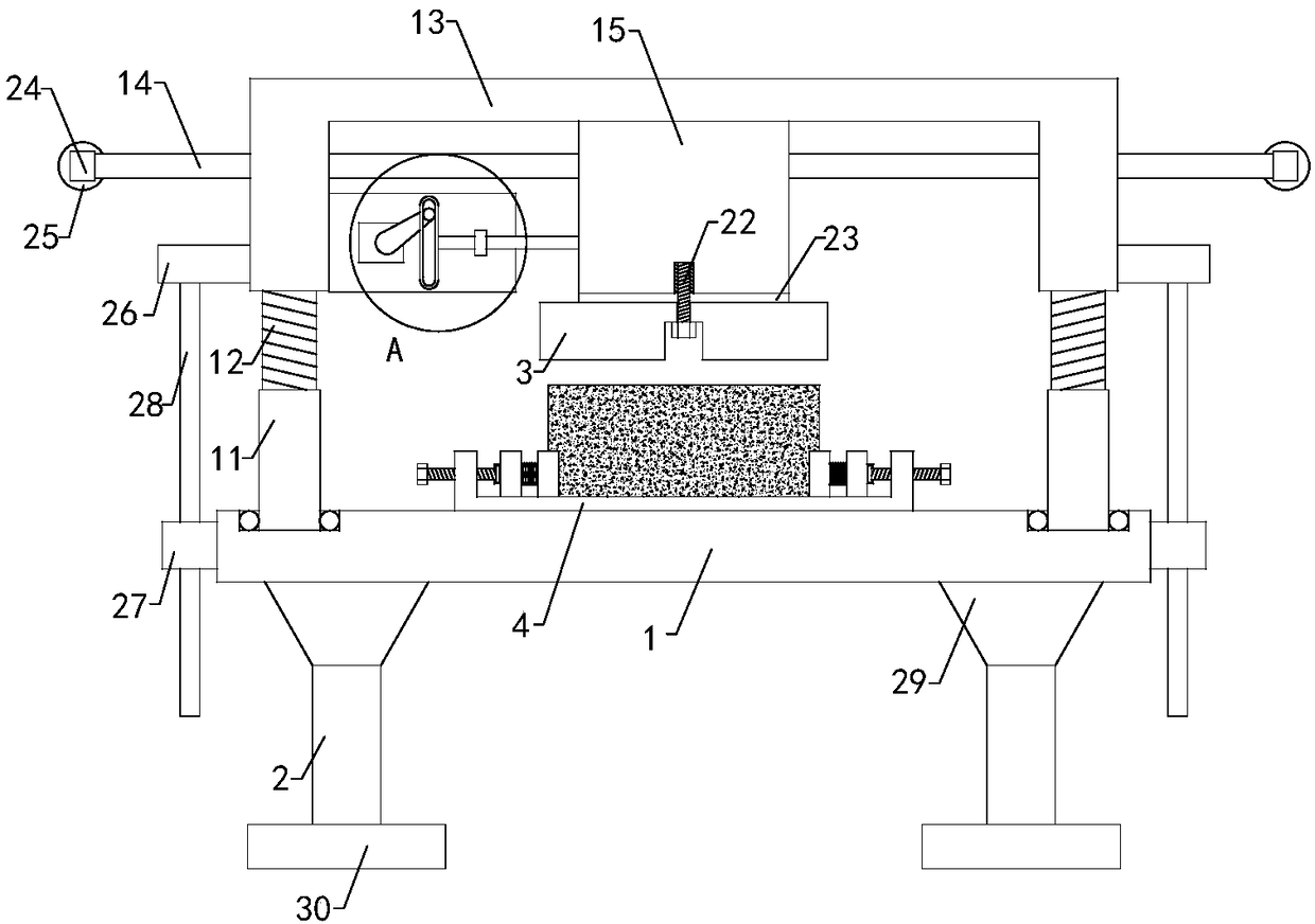
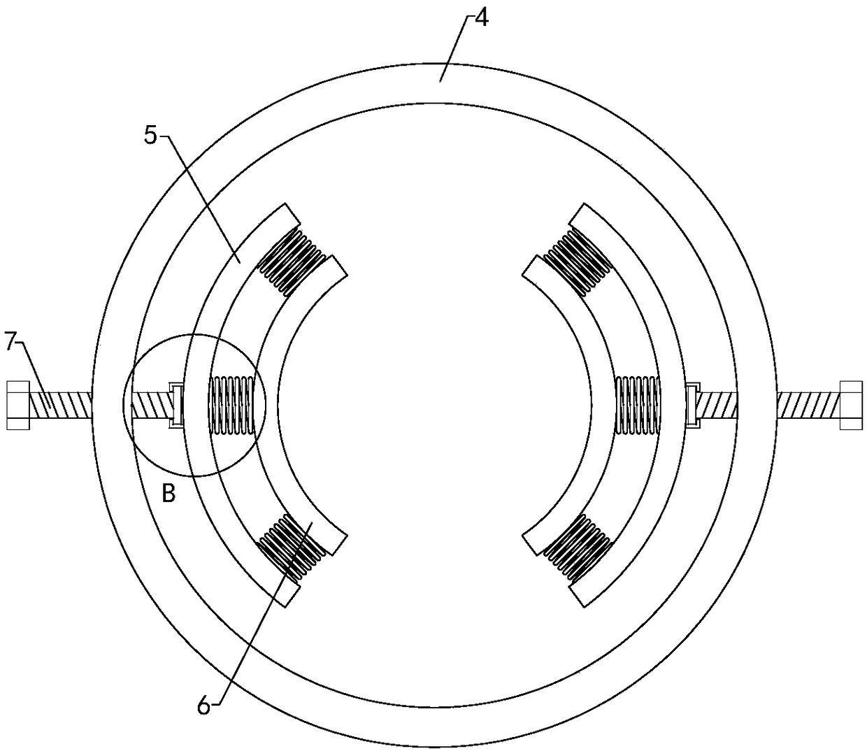
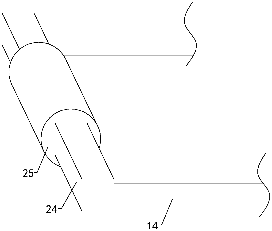
[0021] Such as Figure 1 to Figure 6As shown, a surface grinding device for wafer production and processing of the present invention includes a workbench 1 and four sets of legs 2, and the tops of the four sets of legs are respectively connected to the left front side, left rear side, and right front of the bottom end of the workbench. The side and the right rear side are connected, and the top right side of the workbench is placed with a grinding disc 3; including a fixed disc 4, a left arc-shaped adjustment plate 5, a right arc-shaped adjustment plate, a left arc-shaped splint 6, a right arc-shaped splint, a left Adjusting bolt 7, right adjusting bolt, left limit ring 8...


PUM


Abstract

The invention relates to the technical field of accessory devices, in particular to a surface grinding device for wafer producing and processing. The surface grinding device can improve the clamping effect, can adapt clamping of wafer slicing with different sizes, and meanwhile the wafer slicing is prevented from being damaged in the clamping process; and the surface grinding device does not needthat a polishing sand tray is manually used to polish the surface of the top end of the wafer slicing, manpower is saved, the levelness of a polishing surface can be guaranteed, the polishing effect is improved, and the practicability is improved. The surface grinding device comprises a workbench, four groups of support legs, a fixing disk, a left arc-shaped adjusting plate, a right arc-shaped adjusting plate, a left arc-shaped clamping plate, a right arc-shaped clamping plate, a left adjusting bolt, a right adjusting bolt, a left limiting ring, a right limiting ring, multiple groups of left buffer springs, multiple groups of right buffer springs, two groups of left threaded pipes, two groups of left threaded rods, two groups of right threaded pipes, two groups of right threaded rods, a fixing block, two groups of left limiting square columns, two groups of right limiting square columns, a moving block, a driving motor, a rocker arm, a annular adjusting ring, a mounting plate, a limiting ring and a telescopic rod.

Description

technical field [0001] The invention relates to the technical field of accessory devices, in particular to a surface grinding device for wafer production and processing. Background technique [0002] As we all know, the surface grinding device used for wafer production and processing is a kind of grinding of the knife marks and concave-convex surfaces caused by slicing on the surface of the wafer slices after slicing, so as to better regulate the thickness of the wafer slices and reduce the gap between slices and slices. The thickness difference between them and the auxiliary device for improving the parallelism have been widely used in the field of wafer production and processing; the existing surface grinding device for wafer production and processing includes a workbench, four sets of legs, Placement plate, left clamping plate and right clamping plate, the tops of the four sets of outriggers are respectively connected with the left front side, left rear side, right front ...

Claims


Application Information

Patent Timeline
IPC IPC(8): H01L21/02H01L21/304B24B37/27B24B37/34
CPCH01L21/02H01L21/304B24B37/27B24B37/34
Inventor 王昌华
Owner 江苏英锐半导体有限公司
Why Eureka
Try Eureka