
Chip synchronous rectification device

A synchronous rectification and device technology, applied in electric solid state devices, semiconductor devices, semiconductor/solid state device components, etc., can solve the problems of many peripheral components, high cost, and large PCB area, so as to improve production efficiency and avoid damage. , The effect of preventing the phenomenon of open connection

Pending Publication Date: 2018-11-30
JINAN JINGHENG ELECTRONICS
View PDF0 Cites 0 Cited by
  • Summary
  • Abstract
  • Description
  • Claims
  • Application Information

AI Technical Summary

Problems solved by technology

At present, most synchronous rectification circuits are composed of three parts: MOSFET devices, control circuits and energy storage components. When in use, the three parts are directly welded on the PCB board. There are many peripheral components, occupying a large PCB area, and the cost is relatively high.

Method used


Image

  • Chip synchronous rectification device
  • Chip synchronous rectification device
  • Chip synchronous rectification device

Examples


Embodiment Construction

[0015] The present invention will be further described below in conjunction with the accompanying drawings and specific embodiments.

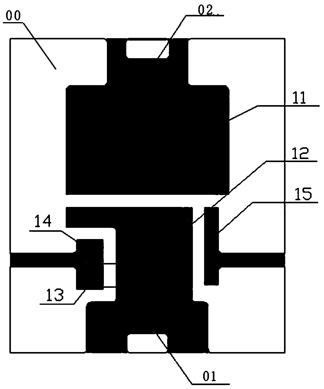
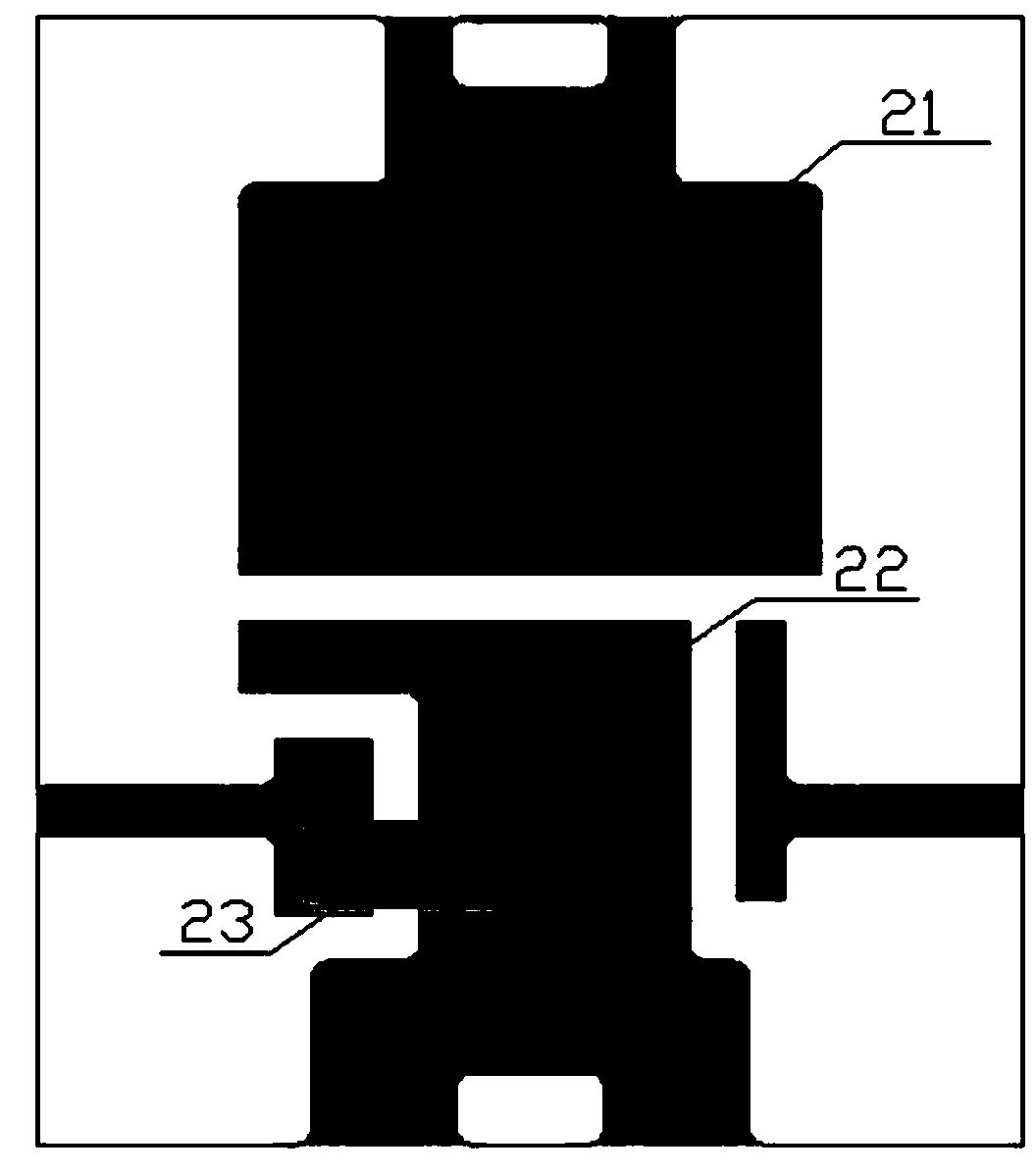
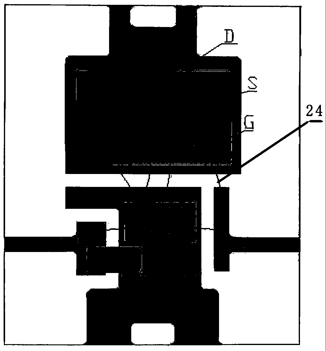
[0016] A chip type synchronous rectification device, including a metal frame 00, such as figure 1 As shown, it includes a schematic diagram of a metal frame 00. The metal frame 00 is provided with a positive electrode 01 and a negative electrode 02 of a chip synchronous rectification device. The metal frame 00 is also provided with a MOSFET chip bonding area 11, a control IC chip bonding area 12, and a battery. The energy element bonding area 13, the first transition bonding area 15 and the second transition bonding area 14, the control IC bonding area 12 is connected to the negative pole 02 of the chip synchronous rectification device, the energy storage element bonding area 13 is connected to the chip synchronous rectification device The positive pole 01 is connected.

[0017] Such as figure 2 , 3 As shown, the drain D of the MOSFET chip ...


PUM


Abstract

The invention discloses a chip synchronous rectification device. A MOSFET chip, a control IC chip and an energy storage component are integrated on a metal frame; the shape is packaged in a chip manner by means of a small epoxy packaging body; the board size occupied by the boundary dimension is equivalent to a single rectifier diode on the PCB board, which can directly replace the single rectifier diode; therefore, users increase the synchronous rectification function without increasing the PCB area, the cost is reduced significantly, and the productivity is improved significantly; a first transition bonding area and a second transition bonding area are arranged on the metal frame, the first bonding point is on the chip, and the second bonding point is on the metal frame, so as to avoid damages to the chip of the chopper in the bonding process, ensure that the bonding wire tension meets the requirements, prevent the connection from opening, and improve the yield and reliability of thechip synchronous rectifier device.

Description

technical field [0001] The invention relates to a chip type synchronous rectification device, which belongs to the field of power AC and DC conversion. Background technique [0002] At present, the field of power AC and DC conversion technology is developing rapidly, and synchronous rectification circuits are replacing rectifier tubes. In the case of low voltage and high current output, the conduction voltage drop VF of the rectifier is relatively high, and the loss of the rectifier at the output end is particularly prominent. The turn-on voltage drop VF of the fast recovery diode (FRD) or ultra-fast recovery diode (SRD) can reach 1.0~1.2V, even if a low-drop Schottky diode (SBD) is used, a voltage drop of about 0.6V will be generated. This results in increased rectification losses and reduced power supply efficiency. The on-state resistance of the power MOSFET is very low, and the conduction voltage drop is relatively small, generally only about 0.006V, which can improve ...

Claims


Application Information

Patent Timeline
Patent Type & Authority Applications(China)
IPC IPC(8): H01L25/16H01L23/495H01L23/31
CPCH01L25/16H01L23/3121H01L23/49513H01L2924/181H01L2224/48091H01L2224/48247H01L2924/00014H01L2924/00012
Inventor 李继远张庆猛崔同张洪亮季群王丽祁伟
Owner JINAN JINGHENG ELECTRONICS
Learn More