
Energy storage capacity allocation method used in photovoltaic/energy storage integrated system

A technology of energy storage system and energy storage capacity, applied in photovoltaic power generation, flexible AC transmission system, energy storage, etc., can solve the problems of not considering the specific value of energy storage system energy storage capacity, single type of battery, etc., to reduce charging and discharging times, has the effect of accuracy and prolonging the service life

Active Publication Date: 2018-11-30
ELECTRIC POWER SCI & RES INST OF STATE GRID TIANJIN ELECTRIC POWER CO +3
View PDF3 Cites 5 Cited by
  • Summary
  • Abstract
  • Description
  • Claims
  • Application Information

AI Technical Summary

Problems solved by technology

[0006] At present, most of the batteries used in existing domestic energy storage systems are relatively single, that is, only lead-acid batteries are used as energy storage units, or only lead-carbon batteries are used as energy storage units, and the energy storage system is not considered to stabilize fluctuations. The specific value of the required energy storage capacity
At the same time, the service life of the battery is rarely taken into consideration in the existing domestic technologies

Method used


Image

  • Energy storage capacity allocation method used in photovoltaic/energy storage integrated system
  • Energy storage capacity allocation method used in photovoltaic/energy storage integrated system
  • Energy storage capacity allocation method used in photovoltaic/energy storage integrated system

Examples


Embodiment Construction

[0047] Embodiments of the present invention are described in further detail below in conjunction with the accompanying drawings:

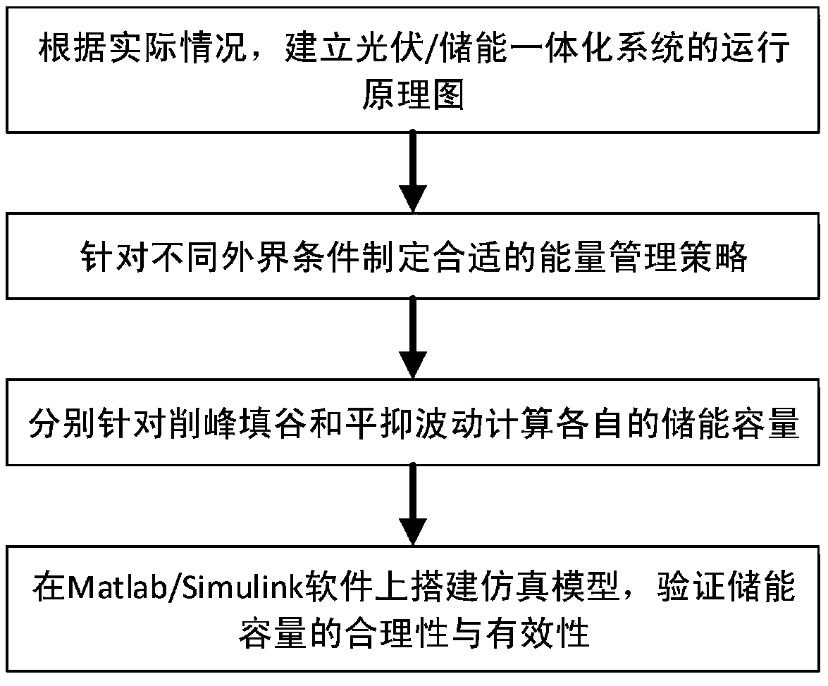
[0048] A method for configuring energy storage capacity in a photovoltaic / energy storage integrated system, such as figure 1 shown, including the following steps:

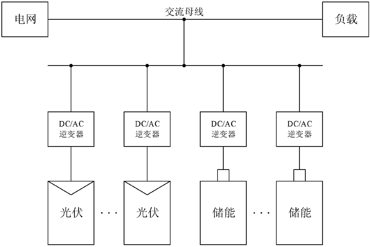
[0049] Step 1. Taking a photovoltaic / energy storage system project in a certain place as a reference, establish a photovoltaic / energy storage integrated system including a lead-acid battery energy storage system and a lead-carbon battery energy storage system, and build a photovoltaic / energy storage integrated system operating schematic diagram .

[0050] In this embodiment, the photovoltaic / energy storage integrated system in step 1 includes a photovoltaic power station system, a lead-acid battery energy storage system, a lead-carbon battery energy storage system, a photovoltaic grid-connected inverter, a three-phase power grid and loads; The photovoltaic power generation unit in the...


PUM


Abstract

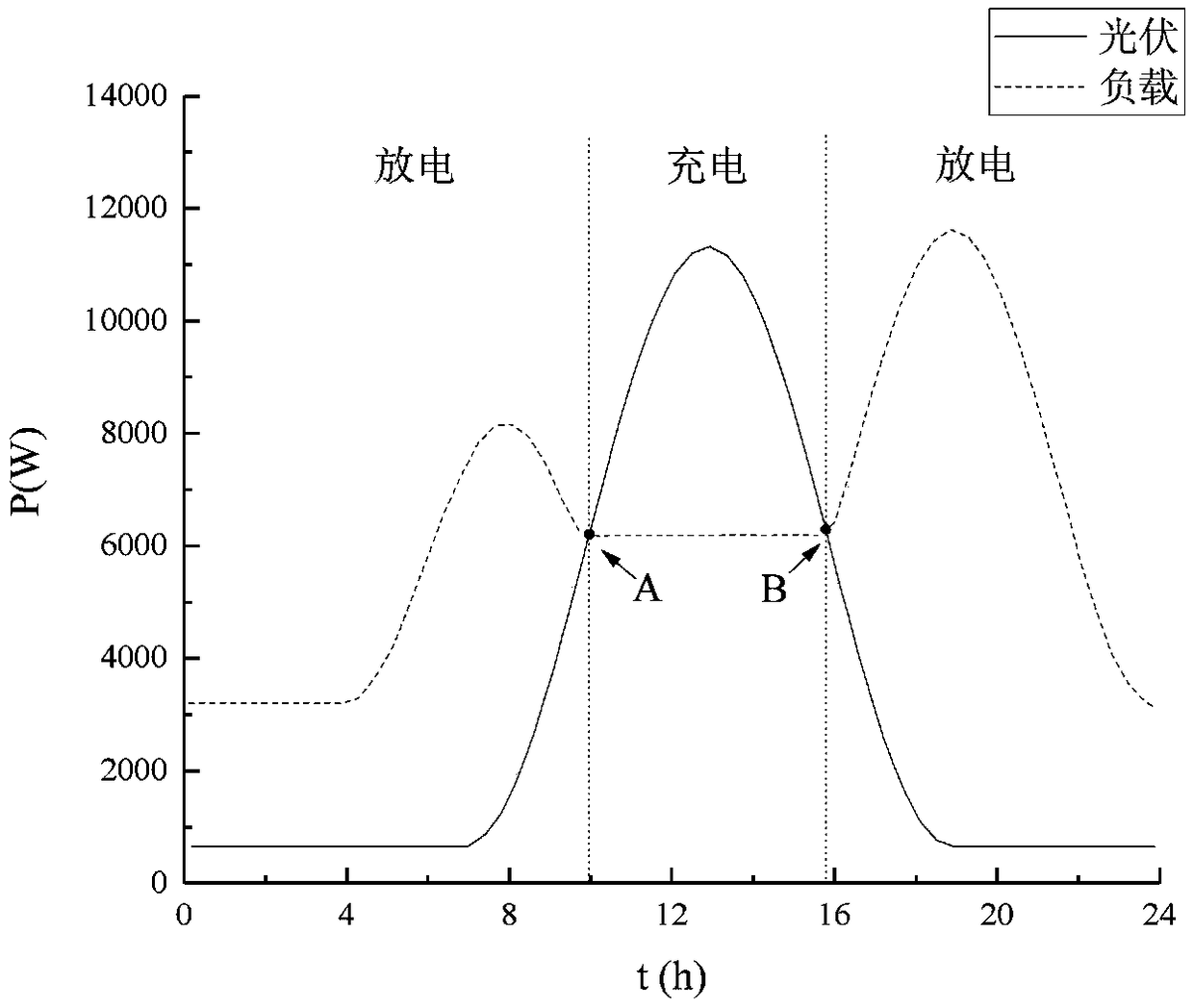
The invention relates to an energy storage capacity allocation method used in a photovoltaic / energy storage integrated system. The method is technically characterized by comprising the following stepsof step 1, taking a certain place of photovoltaic / energy storage system project as a reference, and establishing a photovoltaic / energy storage integrated system comprising a lead-acid battery energystorage system and a lead-carbon battery energy storage system; 2, making a proper energy management strategy to control the lead-acid battery energy storage system and the lead-carbon battery energystorage system separately; step 3, establishing a lead-acid battery energy storage system and a lead-carbon battery energy storage system, wherein the lead-acid battery energy storage system and the lead-carbon battery energy storage system are used for peak clipping and valley filling and fluctuation stabilizing respectively, and performing designing and calculating on the energy storage capacityunder different function conditions; and step 4, after the capacities of the energy storage system are obtained when the system conducts peak clipping and valley filling and fluctuation stabilizing respectively, building a corresponding simulation model for simulation. The lead-acid battery and the lead-carbon battery are combined to serve as an energy storage system, and the energy storage system is controlled to perform peak clipping and valley filling and fluctuation stabilizing through an appropriate energy management strategy.

Description

technical field [0001] The invention belongs to the technical field of new energy management, and relates to a method for configuring energy storage capacity, in particular to a method for configuring energy storage capacity in a photovoltaic / energy storage integrated system. Background technique [0002] After the 1970s, with the development of modern industry, the global energy crisis and air pollution problems have become increasingly prominent. Traditional fuel energy is decreasing day by day, and the harm to the environment is becoming more and more prominent. At the same time, about 2 billion people in the world do not have access to normal energy supply. At this time, solar energy has become the focus of attention due to its unique advantages. Abundant solar radiant energy is an important energy source, inexhaustible, non-polluting, cheap, and freely usable by human beings. Its potential for development and utilization is very broad. However, as photovoltaic power g...

Claims


Application Information

Patent Timeline
Patent Type & Authority Applications(China)
IPC IPC(8): H02J3/32H02J3/38
CPCH02J3/383H02J3/32H02J2203/20Y02B10/10Y02E10/56Y02E40/10Y02E70/30Y02A30/60
Inventor 霍现旭严晶晶赵宝国赵洪磊王剑锋项添春马世乾李树鹏李淋孙璐王凯徐青山范瑜恺
Owner ELECTRIC POWER SCI & RES INST OF STATE GRID TIANJIN ELECTRIC POWER CO
Learn More