
A time-sharing carbon dioxide capture storage system for a thermal power plant

A carbon dioxide and storage system technology, applied in the field of energy storage and energy saving, can solve the problems of power grid load-shaving and valley-filling, large heat and electric energy consumption, and achieve peak-shaving and valley-filling, work reduction, and the effect of alleviating the contradiction between power supply and demand

Active Publication Date: 2021-01-12
INST OF ENGINEERING THERMOPHYSICS - CHINESE ACAD OF SCI
View PDF7 Cites 0 Cited by
  • Summary
  • Abstract
  • Description
  • Claims
  • Application Information

AI Technical Summary

Problems solved by technology

[0005] Aiming at the problem that the compression and precipitation of carbon dioxide in the existing post-combustion carbon dioxide capture system consume a lot of heat energy and electric energy, the purpose of this invention is to analyze the carbon dioxide in the flue gas of the power plant according to the changing law of residential and industrial electricity consumption. At the same time, use the power generated by the power plant during the low power consumption period and the heat energy of the steam turbine extraction during the low power consumption period. By reasonably arranging the power consumption and steam extraction of the power plant during the peak and valley periods, this will help the power grid Peak shaving and valley filling, so that more renewable energy such as wind power and photovoltaics can be accommodated online, and the relationship between power supply and demand can be eased

Method used


Image

  • A time-sharing carbon dioxide capture storage system for a thermal power plant
  • A time-sharing carbon dioxide capture storage system for a thermal power plant

Examples


Embodiment Construction

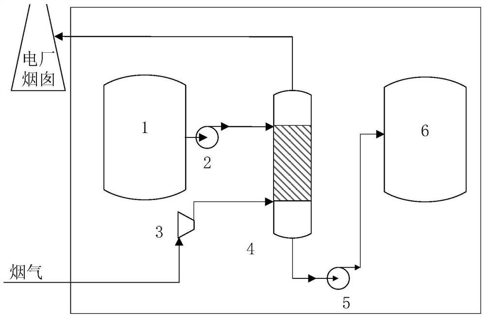
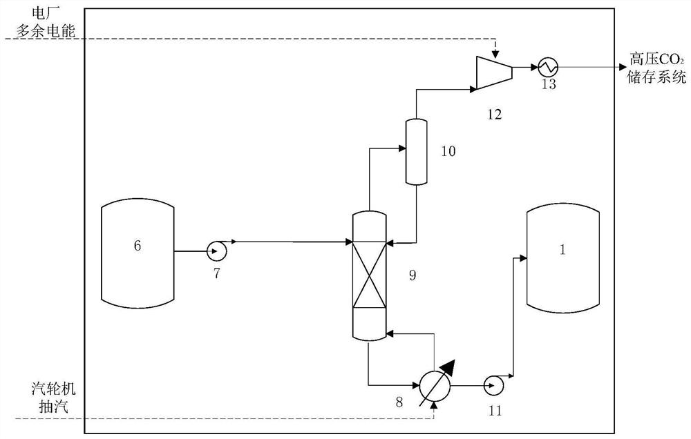
[0033] In order to make the purpose, technical solutions and advantages of the present invention clearer, the following embodiments are given in conjunction with the accompanying drawings to describe in detail that the purpose of the present invention is completely and effectively achieved by the above-mentioned embodiments. Those skilled in the art can understand that the present invention includes but is not limited to the contents described in the accompanying drawings and the above detailed description. Although the present invention has been described with respect to the embodiments currently considered to be the most practical and preferred, it should be understood that the present invention is not limited to the disclosed embodiments, and any modifications that do not depart from the functional and structural principles of the present invention will be included in the claims. in the range.

[0034] like figure 1 , 2 As shown, the time-sharing carbon dioxide capture an...


PUM


Abstract

The invention discloses a time-shared carbon dioxide trapping and storing system of a thermal power plant. According to the system, the action of power-grid peak-load shifting of the power plant can be effectively improved through reasonably arranging peak-valley-moment power utilization and steam extraction of the power plant so as to accommodate more renewable energy sources to be on a grid. Thedevice mainly comprises components such as a lean solution storage tank, a pregnant solution storage tank, an absorption column, a stripper, a reboiler, a separator, a carbon dioxide compressor and acarbon dioxide cooler. At a power utilization peak time, the system runs under a carbon dioxide absorption working condition, at this time, carbon dioxide in flue gas is trapped and stored in a pregnant solution (carbon dioxide absorbed absorption solution) under the condition of consuming a small amount of station-service power; and at a power utilization valley time, the system runs under a carbon-dioxide resolving working condition, at this time, a large volume of steam turbine extracted steam is required to be consumed to resolve the carbon dioxide in the pregnant solution into a gaseousstate, and the gaseous-state carbon dioxide is compressed into a high-pressure state under normal pressure by consuming a large amount of station-service power and is stored.

Description

technical field [0001] The invention belongs to the technical field of energy storage and energy saving, and relates to a carbon dioxide capture and storage system, in particular to a time-sharing carbon dioxide capture and storage system for thermal power plants. The thermal energy possessed by the steam turbine extraction during the period of low electricity and electricity consumption. The carbon dioxide in the flue gas is stored in the carbon dioxide absorption liquid during the peak period of electricity consumption, and the carbon dioxide is separated from the carbon dioxide absorption liquid and compressed and stored by using the excess heat and electricity in the power plant during the low power consumption period. Compared with the non-time-sharing system, it can realize peak shaving and valley filling of electric energy, and accommodate more renewable energy to be connected to the grid. Background technique [0002] In China, which is at the critical stage of larg...

Claims


Application Information

Patent Timeline
Patent Type & Authority Patents(China)
IPC IPC(8): B01D53/14
CPCB01D53/1475Y02A50/20Y02C20/40
Inventor 郭丛徐玉杰汪翔陈海生
Owner INST OF ENGINEERING THERMOPHYSICS - CHINESE ACAD OF SCI
Learn More