

Chemical raw material mixing tank with lifting and stirring device
A chemical raw material and stirring device technology, which is applied to mixers with rotating stirring devices, mixers, mixer accessories, etc., can solve the problems of easy accumulation of raw materials and inconvenient feeding, so as to avoid accumulation, facilitate feeding and mixing Efficient effect
- Summary
- Abstract
- Description
- Claims
- Application Information
AI Technical Summary
Problems solved by technology
Method used
Image

Examples
Embodiment 1
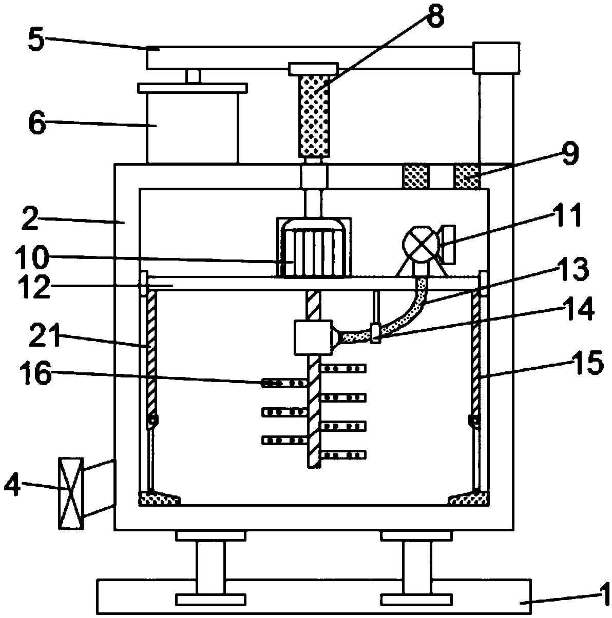
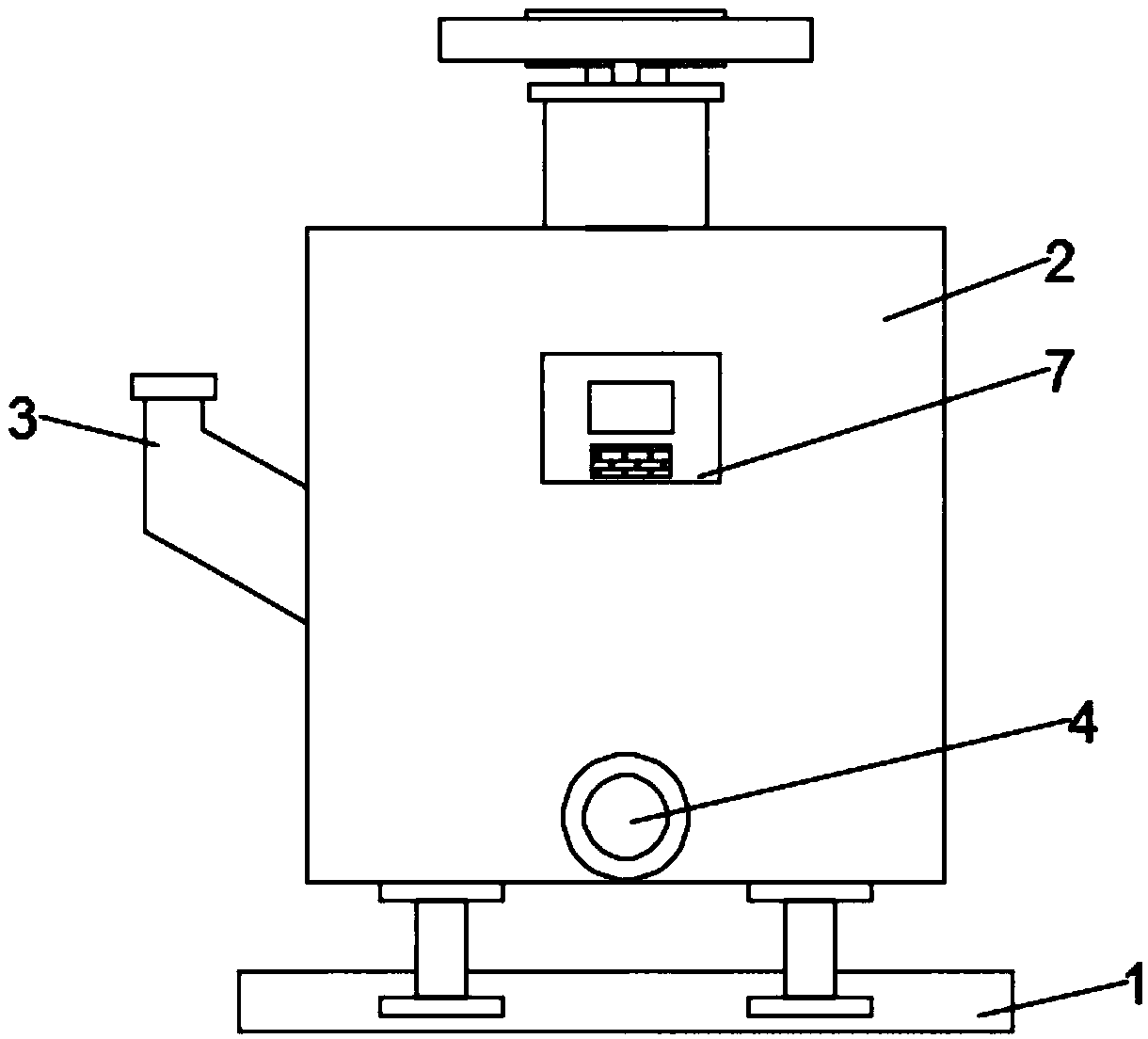
[0019] see Figure 1~4 , in an embodiment of the present invention, a chemical raw material mixing tank with a lifting and stirring device includes a support base 1, a tank body 2, a lifting plate 12, a scraper assembly 15 and a stirring assembly 16, and a tank is arranged above the support base 1 Body 2, support legs are welded at the four corners of the bottom surface of the tank body 2, the support legs are fixed on the support base 1, a support bar 5 is arranged in parallel above the tank body 2, and the right end of the support bar 5 is connected to the tank body 2. Welding, the top of the rear wall of the tank body 2 is provided with a feeding port 3, the feeding port 3 communicates with the tank body 2, and the bottom of the left side wall of the tank body 2 is provided with a discharge port 4, and the discharge port 4 The port 4 communicates with the inner cavity of the tank body 2, and the top of the inner cavity of the tank body 2 is slidably installed with a lifting...
Embodiment 2
[0029] Such as Figure 4 As shown, in this embodiment, the stirring net 24 and the second scraper 22 are connected in a rotational manner, so that the stirring net can be driven when the second scraper 22 rotates around the hinge shaft 23 24 rotations, the stirring effect has been strengthened, and other structures are identical with embodiment 1 in the present embodiment.
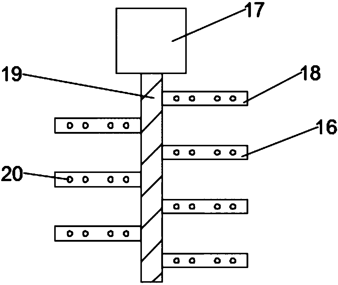
[0030] The working principle of the present invention is: the raw material is sent into the inner cavity of the tank body 2 through the feeding port 3, the control panel 7 controls the start of the hydraulic cylinder 8, the working motor 10 and the exhaust fan 11, and the hydraulic cylinder 8 drives the The working motor 10 and the lifting plate 12 move up and down, and the working motor 10 drives the stirring assembly 16 to rotate, so as to rotate and stir the raw materials in the inner cavity of the tank body 2 up and down, and at the same time, the lifting plate 12 moves up and down to drive the The firs...
PUM
 Abstract
Description
Claims
Application Information