
A tooling structure that can realize stable clamping of any axial-flow blade

A blade and tooling technology, applied in the field of axial flow impeller machinery blade processing and inspection, can solve the problems of reducing the progress of inspection, a large number of tooling, waste of resources and costs, and achieve efficient design, shorten inspection cycles, and reduce inspection costs. Effect

Active Publication Date: 2019-07-12
INST OF ENGINEERING THERMOPHYSICS - CHINESE ACAD OF SCI
View PDF11 Cites 0 Cited by
  • Summary
  • Abstract
  • Description
  • Claims
  • Application Information

AI Technical Summary

Problems solved by technology

As a result, the number of tooling is very large. For example, for a 10-level blade row, at least 20 tooling are required, and they can only be used for this engine, which undoubtedly causes a great waste of resources and a sharp increase in cost.
On the other hand, in some cases, it is necessary to entrust a professional third party to carry out more accurate detection. In this case, the third party does not have the exact structure of the blade. If a special tooling is designed, the clamping problem of the part detection can be solved , but it will undoubtedly reduce the progress of detection and bring waste of cost

Method used


Image

  • A tooling structure that can realize stable clamping of any axial-flow blade
  • A tooling structure that can realize stable clamping of any axial-flow blade
  • A tooling structure that can realize stable clamping of any axial-flow blade

Examples


Embodiment Construction

[0027] In order to make the object, technical solution and advantages of the present invention clearer, the present invention will be further described in detail below with reference to the accompanying drawings and examples.

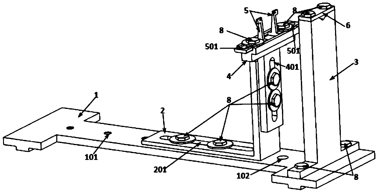
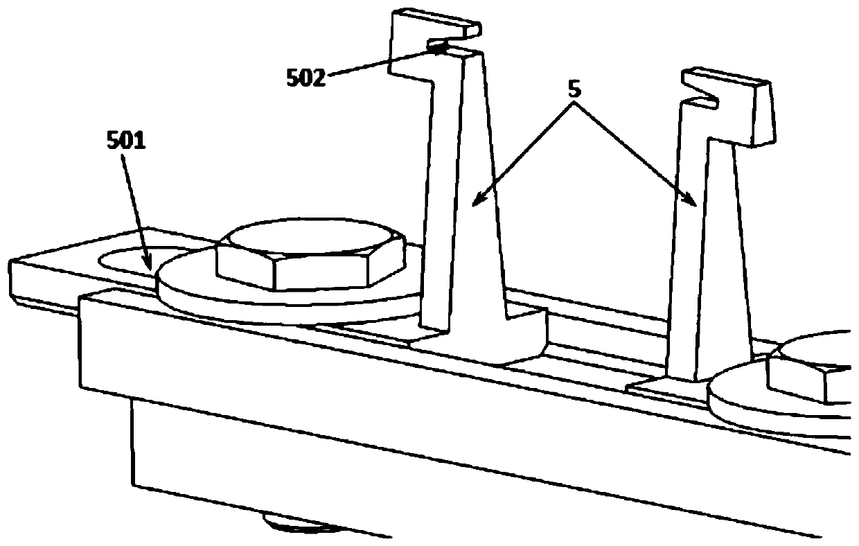
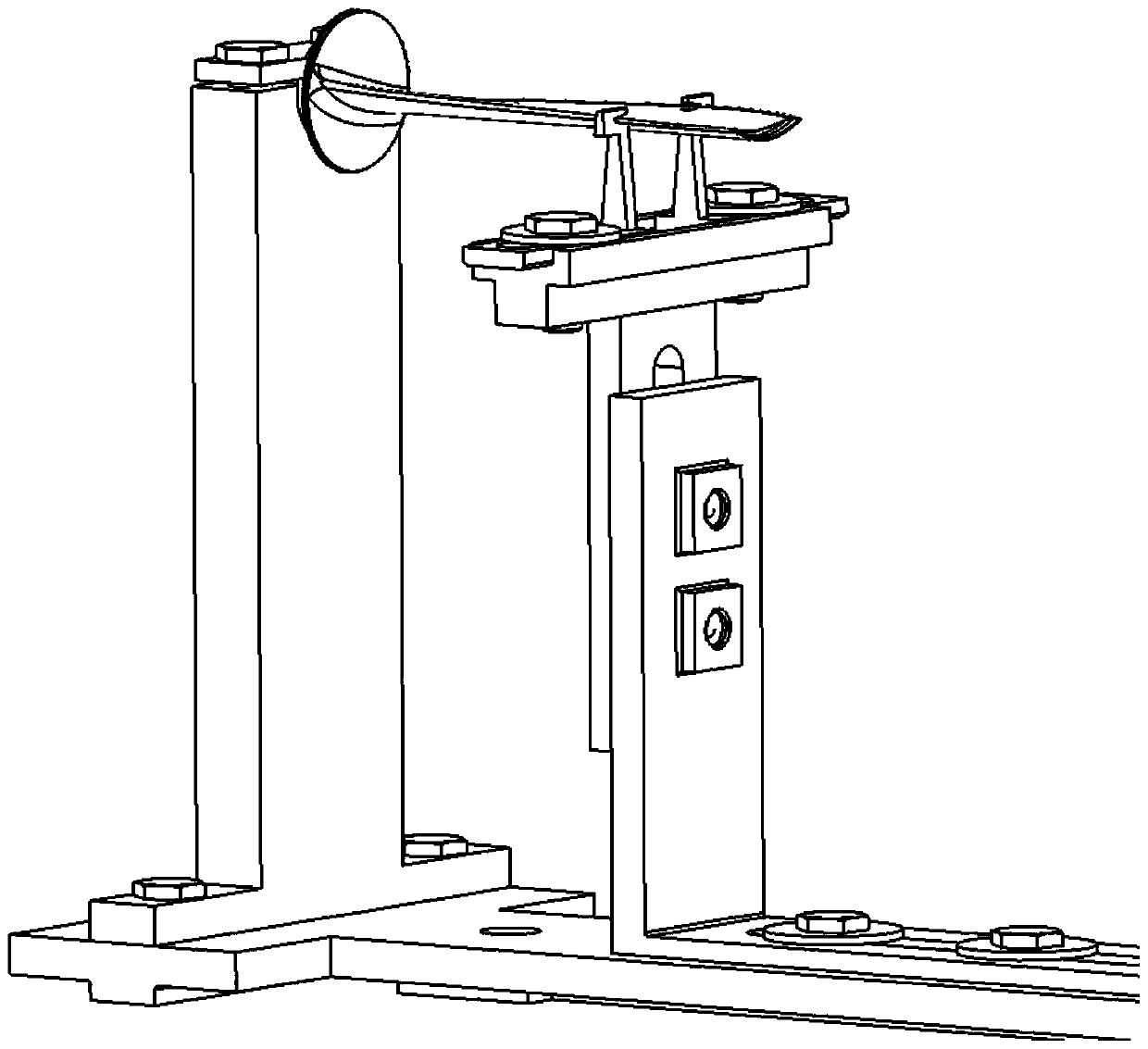
[0028] Such as figure 1 , 2 As shown, the tooling structure of the present invention that can realize the stable clamping of any axial-flow blade includes a base 1 and a movable bracket 2 and a fixed bracket 3 arranged on the base 1 . The base 1 is provided with a plurality of through holes 102, and the base 1 is fixed on the detection platform or the processing platform through the through holes 102 and the fasteners 8 arranged in the through holes 102, so as to ensure that the whole set of tooling will not be damaged during use. move. The bottom of the fixed bracket 3 is fixedly arranged on the base 1, and the top of the fixed bracket 3 is provided with a V-shaped groove designed and matched with a compression cover plate 6 to realize the fixing of ...


PUM


Abstract

The invention discloses a tool structure for realizing stable clamping of any axial flow blade. The tool structure comprises a base as well as a movable bracket and a fixed bracket arranged on the base; blades with different lengths can be fixed through adjusting the position of the movable bracket; blades with different cambers can be fixed through adjusting the position of a height adjusting seat; blades with different widths can be fixed through adjusting the position between two width adjusting seats; and blades with different thicknesses can be fixed through the depths, clamped in a wedge-shaped opening structure, of the leading edge and the trailing edge of a blade. The tool structure can realize stable clamping of the blade with any length, width, thickness and torsional angle, is high in adaptability and greatly lowers the detecting cost; all components can be disassembled and replaced, so that when the existing tool cannot meet the requirement or the component abrasion is moreserious, the usable or replaceable components can be efficiently designed and produced, and the detecting period is greatly shortened.

Description

technical field [0001] The invention relates to the field of processing and testing of blades of axial-flow impeller machinery, and relates to a tooling structure capable of realizing stable clamping of any axial-flow blade. Stable clamping is of great engineering significance for blade machining of axial flow turbomachinery. Background technique [0002] Inside a rotary turbomachinery, an axial-flow aerodynamic design is often used. This aerodynamic design includes rotor blades that rotate around an axis of rotation and relatively stationary stator blades. The deviation between the actual working profile of the axial flow rotor blade and the stator blade and the design state determines the efficiency and performance of the components. For blades with a short height, thanks to good rigidity, sufficient precision requirements can be guaranteed during processing; however, for large-scale turbomachinery engines such as large aeroengines, heavy gas turbines, and steam turbines,...

Claims


Application Information

Patent Timeline
Patent Type & Authority Patents(China)
IPC IPC(8): B23Q3/06B25B11/00
CPCB23Q3/062B25B11/00
Inventor 刘军杜强柳光王沛高金海刘红蕊冯引利廉曾妍蒋文婷徐庆宗杨晓洁
Owner INST OF ENGINEERING THERMOPHYSICS - CHINESE ACAD OF SCI
Learn More