Energy gradient utilization multi-energy complementary heat supply system and heat supply method

A heat supply system and energy technology, applied in multi-energy complementary heat supply systems and heat supply fields, can solve the problems of increasing the amount of supplementary heat from high-quality heat sources, incomplete matching, and increased use of high-quality heat degradation, so as to benefit the power grid Peak shaving, reducing the average temperature difference between cold and heat sources, and improving the performance of heat pumps

Pending Publication Date: 2018-12-04
SHANXI SANHESHENG IND TECH +2
View PDF8 Cites 4 Cited by
  • Summary
  • Abstract
  • Description
  • Claims
  • Application Information

AI Technical Summary

Problems solved by technology

[0005] In addition, the demand for heating load is changeable, and the amount and quality of available external heat sources are also mostly unstable. The heat source and the demand for heating load are often not completely matched at a certain time. If the situation adjusts different heat intake in time, it will often increase the supplementary heat of high-quality heat source, which will increase the degraded use of high-quality heat.

Method used


Image

  • Energy gradient utilization multi-energy complementary heat supply system and heat supply method

Examples


Embodiment 1

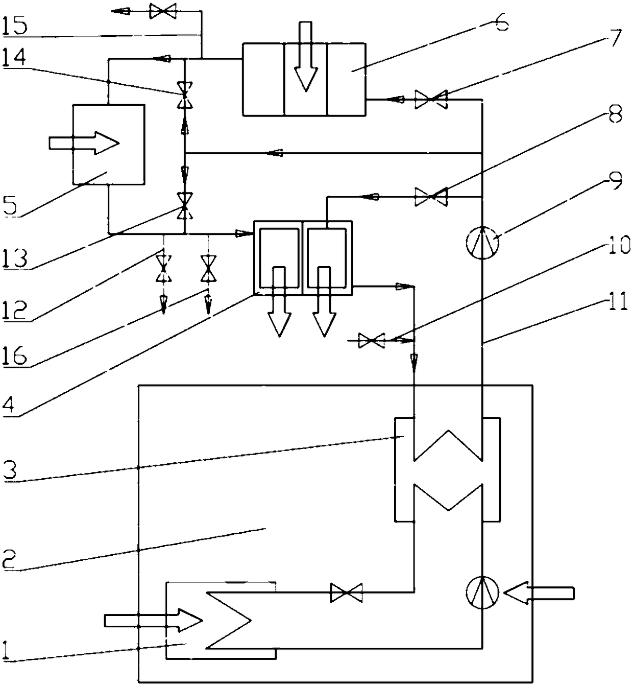
[0046] Such as figure 1 As shown, a multi-energy complementary heating system utilizing cascade energy, the heating system includes a heat pump 2, a low-temperature heater 6, a high-temperature heater 5, a heat user 4, a circulation pump 9 and a circulation pipeline 11;

[0047] The heat pump 2 includes a heat pump evaporator 1 and a heat pump condenser 3; the low-temperature side inlet and outlet of the heat pump condenser 3 are connected to a circulation pipeline 11; the circulation pipeline 11 is sequentially provided with a circulation pump 9, Low temperature heater 6, high temperature heater 5 and heat user 4.

[0048] The heating system is provided with a heater bypass pipeline, one end of the heater bypass pipeline is connected between the heat user 4 and the high-temperature heater 5 on the circulation pipeline 11, and the other end is connected to the circulation pipe Between the low-temperature heater 6 and the circulating pump 9 on the pipeline 11, a rear diverter ...

Embodiment 2

[0062] The heating method based on embodiment 1 system comprises the following steps:

[0063] High-quality energy drives the heat pump 2 to perform a thermodynamic cycle. The heat pump evaporator 1 absorbs heat from the lowest temperature heat source, and then heats up through the heat pump circulation system, so that the absorbed heat and the high-quality energy input by the heat pump enter the heat pump together with the working fluid of the heat pump circulation system On the high temperature side of the condenser 3, in the heat pump condenser 3, the working fluid of the heat pump circulation system transfers the heat to the circulating medium (such as circulating water) from the circulation line 11 on the low temperature side of the heat pump condenser 3;

[0064] The circulating medium on the low-temperature side of the heat pump condenser 3 is driven by the circulating pump 9, heated by the low-temperature heat source through the low-temperature heater 6, and then enters...


PUM


Abstract

The invention discloses an energy gradient utilization multi-energy complementary heat supply system and a heat supply method. The heat supply system comprises a heat pump (2), a low-temperature heater (6), a high-temperature heater (5), a heat user (4), a circulation pump (9) and a circulation pipeline (11), wherein the heat pump (2) comprises a heat pump evaporator (1) and a heat pump condenser(3), an outlet / inlet at the low-temperature side of the heat pump condenser (3) is connected with the circulation pipeline (11), and the circulation pipeline (11) is sequentially provided with the circulation pump (9), the low-temperature heater (6), the high-temperature heater (5) and the heat user (4) in the flowing direction of a medium in the pipeline. According to the energy gradient utilization multi-energy complementary heat supply system and the heat supply method, under the condition that the same heat supply requirement is met, low-quality energy can be fully utilized, and the optimal utilization of high-quality energy can be realized.

Description

technical field [0001] The invention belongs to the field of heating systems, in particular to the technical field of multi-energy complementary heating systems. Specifically, the invention relates to a multi-energy complementary heating system and a heating method for cascaded utilization of energy. Background technique [0002] The water supply temperature of many heating systems is relatively high, but the return water or make-up water temperature of the heating system is low. Traditional heating systems use high-quality energy to directly heat the supply water to the required high temperature, which will increase the irreversible loss of heat transfer and cause Waste of energy quality. [0003] A heat pump can use high-quality electric energy to drive a thermal cycle to improve the quality of low-quality energy. However, the heat pump heating coefficient of performance (energy efficiency ratio COP) is affected by the temperature difference between high and low temperatur...

Claims


Application Information

Patent Timeline
Patent Type & Authority Applications(China)
IPC IPC(8): F24D11/02F25B30/00
CPCF24D11/02F25B30/00
Inventor 郝江平闫润生李小权
Owner SHANXI SANHESHENG IND TECH
Why Eureka
Try Eureka