Automatic honey extractor

A honey machine and motor technology, applied in the field of automatic honey shaker, can solve the problems of low efficiency, cumbersome operation, easy crushing of honeycomb, etc., and achieve the effects of avoiding pollution, reducing cutting resistance, and improving cutting quality

Active Publication Date: 2018-12-07
日照九仙山蜂业有限公司
View PDF6 Cites 2 Cited by
  • Summary
  • Abstract
  • Description
  • Claims
  • Application Information

AI Technical Summary

Problems solved by technology

At present, the cutting method is generally manual cutting, and then put the cut honeycomb into the honey shaker for shaking honey. This method of shaking honey is cumbersome and inefficient.
[0004] In addition, the existing method of fixing

Method used


Image

  • Automatic honey extractor
  • Automatic honey extractor
  • Automatic honey extractor

Examples


Embodiment 1

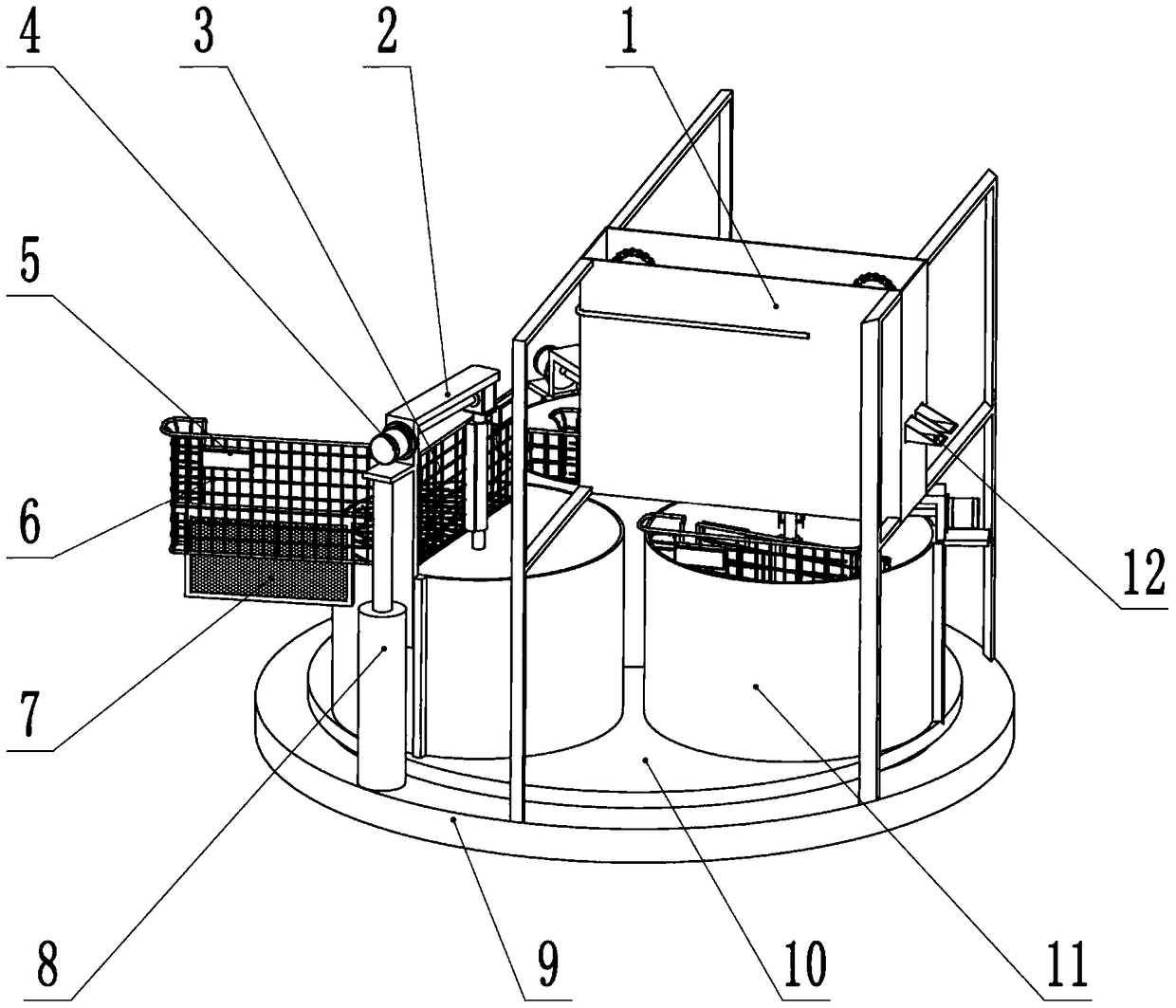
[0021] In embodiment 1, such as Figure 1-7 As shown, the present invention includes a base 9, a wax cap cutting mechanism and a honey shaking mechanism.

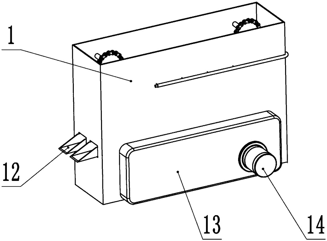
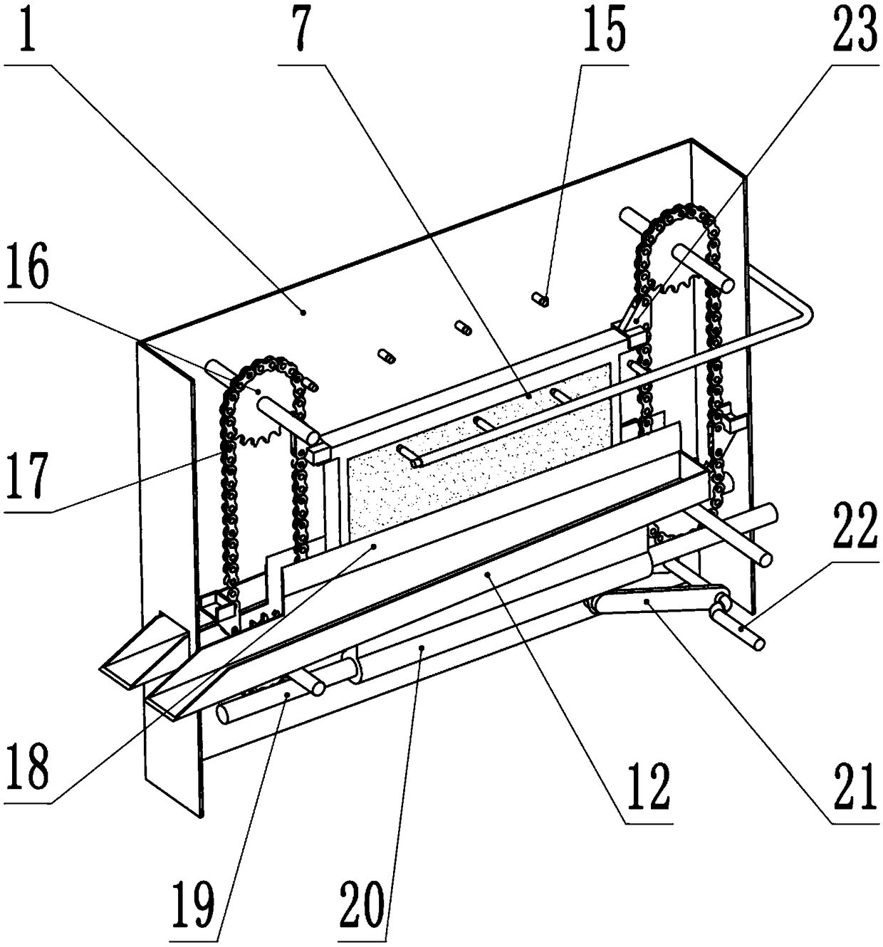
[0022] Such as figure 2 , 3 As shown, the wax cap cutting mechanism includes a housing 1, a No. 1 motor 14, a sprocket 16, a chain 17 structure, a gear box 13, a cutter 18, and a water pump.

[0023] The housing 1 is fixed on the base 9, the upper and lower ends of the housing 1 are respectively provided with openings, and a group of nozzles 15 are respectively arranged on both sides near the upper opening, and the nozzles 15 are driven by a water pump to spray water to the honeycomb 7 wax cap.

[0024] There are two parallel cutters 18 below the nozzle 15 in the housing 1. When the honeycomb 7 is put into the machine, the two cutters 18 are respectively located on both sides of the honeycomb 7, and the honeycomb 7 is cut off by the cutter 18. wax cover. Each of the outer surfaces of the cutters 18 is fixedly provided ...

Embodiment 2

[0035] In Embodiment 2, the main structure of this embodiment is the same as that of Embodiment 1. In this embodiment, the same technical features as those of Embodiment 1 will not be repeated, and only the technical features different from Embodiment 1 will be described.

[0036] Such as Figure 6 As shown, the outer surface of the side wall of the honey bucket 11 is provided with a vertical chute 29 compatible with the vertical bar of the support 2, and the vertical bar is located in the chute 29 and can move vertically along the chute 29 . A horizontal plate 24 is fixed on the vertical bar of the support 2, and a vertical cylinder 8 is arranged on the base 9 below the horizontal plate 24 of the support 2 on the No. 3 station. When the cylinder 8 is inflated, it stretches upward Standing on the horizontal plate 24, the horizontal plate 24 drives the support 2, the grid plate and the honeycomb 7 to move upward.

[0037] When in use, when the honey bucket rotates to the No. ...


PUM


Abstract

The invention discloses an automatic honey extractor, and belongs to the field of agricultural machines. The automatic honey extractor is characterized by comprising a base, a honey cover cutting mechanism and a honey shaking mechanism, the honey cover cutting mechanism comprises a shell, a first motor, chain wheel and chain structures, a gearbox, cutters and a water pump, the two parallel cuttersare arranged on the lower side of a nozzle in the shell, a material guide groove is fixed to the outer side face of each cutter, the two chain wheel and chain structures are located in the shell, a pressing block is arranged on each chain, the honey shaking mechanism is located on the lower side of the honey cover cutting mechanism, the honey shaking mechanism comprises a rotary table, honey barrels, a support, a commutator, a motor, a first grid plate and a second grid plate, and the three honey barrels are evenly distributed on the periphery of the center of the rotary table. Compared withthe prior art, the automatic honey extractor has the advantage that honey cutting and shaking can be automatically completed.

Description

technical field [0001] The invention relates to an agricultural machine, in particular to an automatic honey shaker. Background technique [0002] Honey is the nectar that bees collect from the flowers of flowering plants and brewed in the hive. Bees take nectar or secretions with a water content of about 75% from the flowers of plants and store them in their second stomach. Under the action of various transformations in the body, after about 15 days of repeated brewing, when various vitamins, minerals When the substances and amino acids are enriched to a certain value, the polysaccharides in the nectar are converted into simple sugars glucose and fructose that can be directly absorbed by the human body, stored in the honeycomb and sealed with beeswax. [0003] Beekeepers need to use a honey shaker to obtain honey. Since the outer surface of the hive is covered with a layer of beeswax, the beeswax needs to be cut off before shaking the honey, and then the honey in the hive ...

Claims


Application Information

Patent Timeline
IPC IPC(8): A01K59/04A01K59/00
CPCA01K59/00A01K59/04B26D1/06B26D5/14B26D7/08B26D7/32
Inventor 刘加善
Owner 日照九仙山蜂业有限公司
Why Eureka
Try Eureka