

Exhaust system for industrial waste gas purification equipment
A purification device and technology for industrial waste gas, applied in gas treatment, chemical instruments and methods, use of liquid separation agents, etc., can solve the problems of variable nature, low level, and complex composition of industrial waste gas, so as to achieve efficient recycling and improve purification. effect of effect
- Summary
- Abstract
- Description
- Claims
- Application Information
AI Technical Summary
Problems solved by technology
Method used
Image

Examples
specific Embodiment approach 1
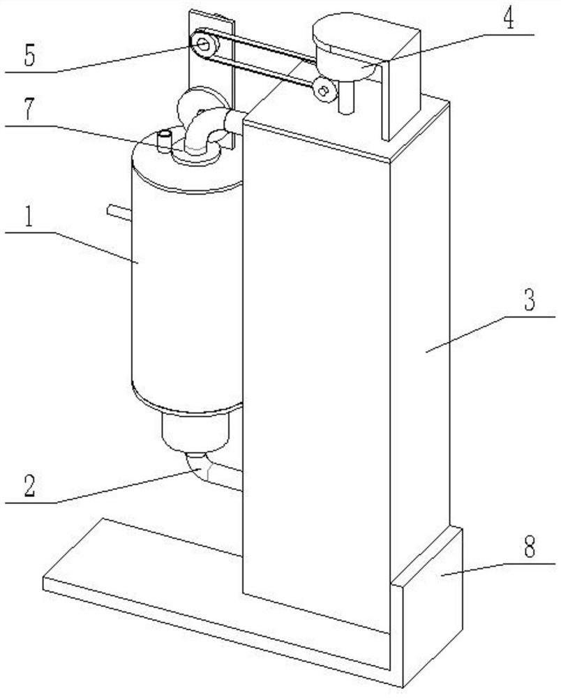
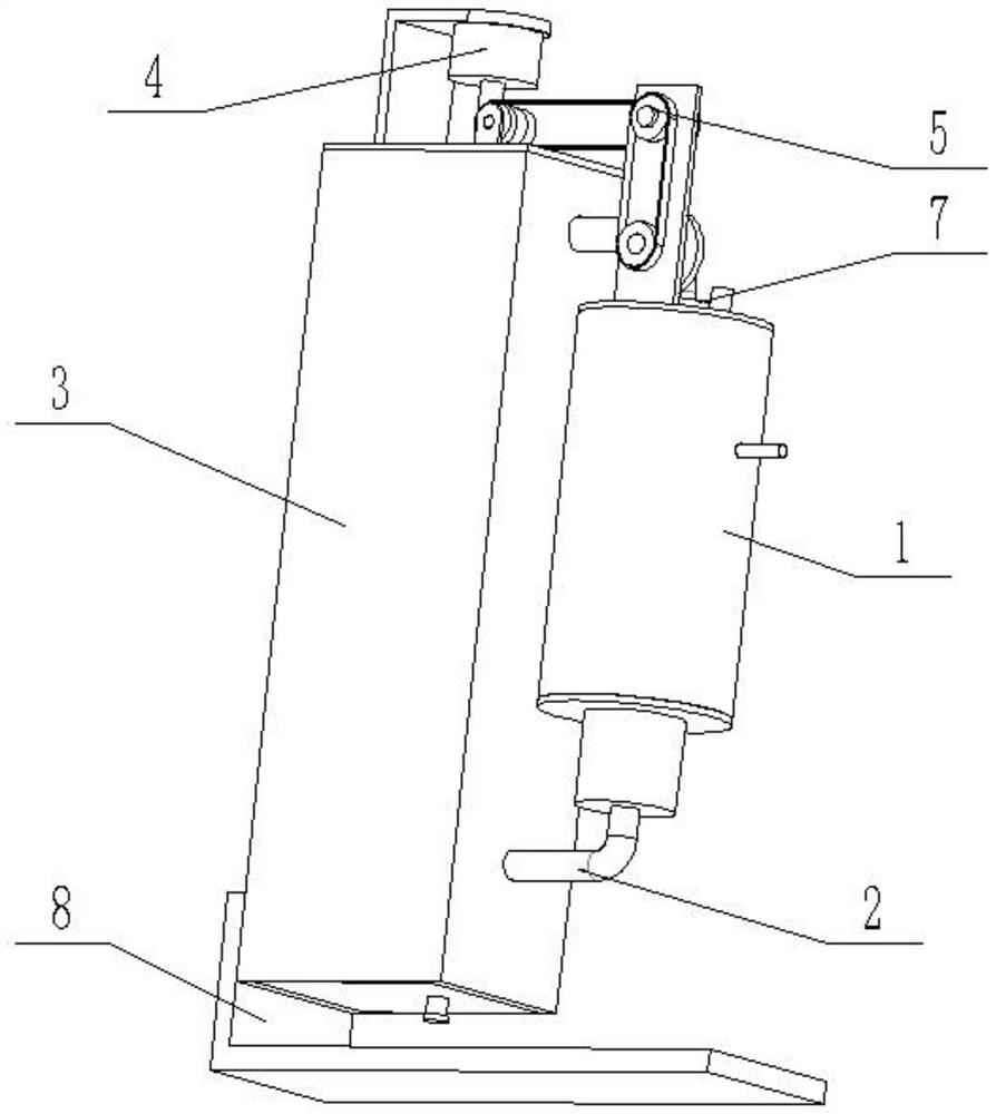
[0034] Such as Figure 1-15As shown, the exhaust system for the industrial exhaust gas purification device includes a spray box 1, a circulation pipe 2, a circulation water tank 3, a circulation controller 4, a transmission wheel 5, a water return device 6, a sprayer 7 and a support seat 8. The lower end of the spray tank 1 is connected to and communicated with the circulating pipe 2, and the lower end of the circulating pipe 2 is inserted into the lower end of the circulating water tank 3; the upper end of the circulating water tank 3 is connected and communicated with the upper end of the shower 7, and the lower end of the shower 7 is inserted into the To the inside of the spray box 1; the circulation controller 4 is fixedly connected to the circulating water tank 3, and the circulation controller 4 is connected to the sprayer 7 through the transmission wheel 5; the circulating water tank 3 is fixedly connected to the support base 8; The circulation controller 4 is connected...
specific Embodiment approach 2
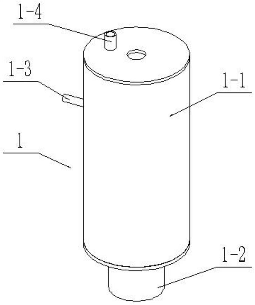
[0036] Such as Figure 1-15 As shown, the spray box 1 includes an upper box body 1-1, a lower box body 1-2, a right-angle air intake pipe 1-3, an exhaust pipe 1-4, a lifting water storage tank 1-5, and a spring rod 1-6 , tension spring 1-7, drainage inner pipe 1-8, drainage outer pipe 1-9 and movable pipe cover 1-10; the lower end of the upper box 1-1 is fixedly connected to the lower box 1-2; The top surface of the upper box body 1-1 is fixedly connected and communicated with the exhaust pipe 1-4, the upper end of the outer surface of the upper box body 1-1 is fixedly connected and communicated with the right-angle air intake pipe 1-3, and the lower end of the right-angle air intake pipe 1-3 The nozzle is inserted into the lower end of the upper box body 1-1, and the lower end nozzle of the right-angle air intake pipe 1-3 is arranged on the inner side of the lifting water storage tank 1-5; the lifting water storage tank 1-5 is connected to the upper box body 1 with clearance ...
specific Embodiment approach 3
[0038] Such as Figure 1-15 As shown, the circulation pipe 2 includes a curved water delivery pipe 2-1, an initial filter cartridge 2-2, an outer ring gear 2-3, a miscellaneous discharge pipe 2-4 and a pipe cover 2-5; the curved water delivery pipe 2- One end of 1 is fixedly connected and connected to the middle of the bottom of the lower box body 1-2; the middle end of the curved water delivery pipe 2-1 is sealed and fixedly connected to the outer surface of the circulating water tank 3, and the other end of the curved water delivery pipe 2-1 passes through The bearing with seat is connected in the middle of the top of the primary filter cartridge 2-2, and the outer surface of the primary filter cartridge 2-2 is fixedly connected to the outer ring gear 2-3; the middle of the bottom end of the primary filter cartridge 2-2 is fixedly connected to discharge Pipe 2-4; the bottom end of the miscellaneous discharge pipe 2-4 is threadedly connected to the cap 2-5; the middle end of ...
PUM
 Abstract
Description
Claims
Application Information