
Automatic thread rolling machine

A thread rolling machine and automatic technology, applied in the field of metal processing, can solve the problems of high cost, low feeding efficiency, easy tooth loss on the head of the rod, etc.

Pending Publication Date: 2018-12-07
海盐龙晟科技股份有限公司
View PDF0 Cites 2 Cited by
  • Summary
  • Abstract
  • Description
  • Claims
  • Application Information

AI Technical Summary

Problems solved by technology

The existing old-fashioned thread rolling machines usually only include a thread rolling mechanism, and the metal rod is manually inserted between the two rolling wheels. After the processing is completed, the rod moves backward to accumulate, which brings: 1. The material efficiency is low, and there are certain safety hazards due to manual feeding; 2. The processing quality is low, especially at the head and tail of the rod, which is prone to tooth loss; 3. The workshop environment is poor, and the cutting fluid is adsorbed on the workpiece , unable to effectively clean up and recycle
For production enterprises, facing the above problems, they can only choose to replace new equipment or even choose imported equipment, which is too expensive

Method used


Image

  • Automatic thread rolling machine
  • Automatic thread rolling machine
  • Automatic thread rolling machine

Examples


Embodiment Construction

[0025] The following is a clear and complete description of the technical solutions in the embodiments of the present invention. Apparently, the described embodiments are only part of the embodiments of the present invention, not all of them. Based on the embodiments of the present invention, all other embodiments obtained by persons of ordinary skill in the art without making creative efforts belong to the protection scope of the present invention.

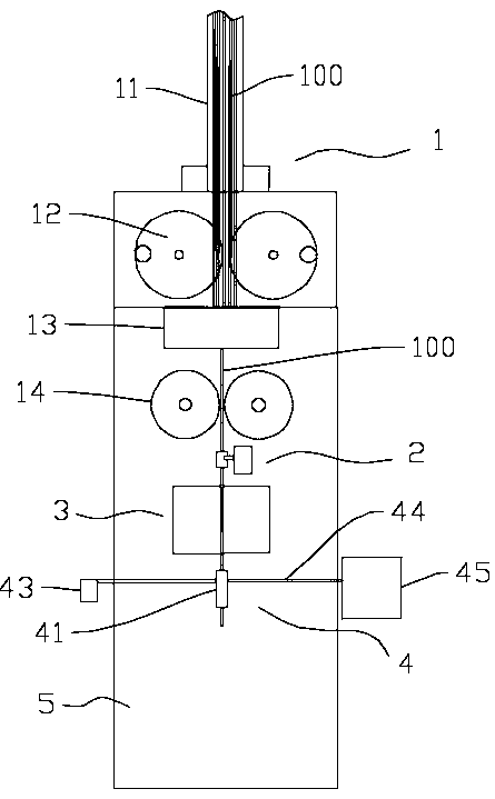
[0026] Such as figure 1 As shown, the present invention provides an automatic thread rolling machine, which possesses: a feeding mechanism 1, including a feeding rack 11, an automatic feeding wheel set 12, a feeding track 13 and a traction roller 14, on which a plurality of workpieces are placed On the material rack 11, a single workpiece is transported to the feeding track 13 by the automatic feeding wheel group 12, and the traction roller 14 is arranged behind the feeding track 13, and the workpiece continues to advance forward...


PUM


Abstract

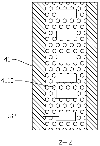
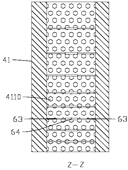
The invention discloses an automatic thread rolling machine. The automatic thread rolling machine comprises a feeding mechanism, a lubricating mechanism, a thread rolling mechanism, a cutting fluid recovery mechanism and a working frame; the feeding mechanism comprises a feeding frame, an automatic feeding wheel set, a feeding rail and traction rollers; the lubricating mechanism is arranged between the traction rollers and the feeding rail, wherein the lubricating mechanism comprises a body and an oil injection port, a channel for allowing a workpiece to pass is formed inside the body, the oilinjection port communicates with the channel, and lubricating oil enters the channel through the oil injection port and is attached to the workpiece; the thread rolling mechanism comprises two wire rolling wheels and a cooling liquid jetting mechanism, and the cooling liquid jetting mechanism comprises a jetting head and a cooling liquid storage box; the cutting fluid recovery mechanism comprisesa shell, an air outlet part, a fan and a backflow pipeline, wherein a through hole allowing the workpiece to pass is formed inside the shell, the bottom of the through hole communicates with the backflow pipeline, and the backflow pipeline leads to the cooling liquid storage tank; and the working frame is used for bearing the mechanisms. According to the automatic thread rolling machine, high-efficiency, high-quality and low-cost thread rolling machining is realized, and the sustainable development direction is provided.

Description

technical field [0001] The invention relates to the field of metal processing, in particular to an efficient and low-cost automatic thread rolling machine. Background technique [0002] The thread rolling machine is a multi-functional cold extrusion forming machine tool. The thread rolling machine can process the thread, straight grain and oblique grain rolling of the workpiece under the cold state within its rolling pressure range; straight teeth, helical teeth and helical spline gears rolling; straightening, reducing, rolling and various forming rolling. The existing old-fashioned thread rolling machines usually only include a thread rolling mechanism, and the metal rod is manually inserted between the two thread rolling wheels. After the processing is completed, the rod moves backward to accumulate, which brings: 1. The material efficiency is low, and there are certain safety hazards due to manual feeding; 2. The processing quality is low, especially at the head and tail...

Claims


Application Information

Patent Timeline
Patent Type & Authority Applications(China)
IPC IPC(8): B21H9/02B21H3/04
CPCB21H3/04B21H9/02Y02P70/10
Inventor 赵建飞
Owner 海盐龙晟科技股份有限公司
Learn More