Oil tank rotation clamp

A technology for rotating fixtures and oil tanks, which is used in manufacturing tools, auxiliary devices, coatings, etc., can solve the problems of oil tank vibration, instability, uneven mass distribution, etc., to meet production needs, simple structure, and uniform weight distribution. Effect

Inactive Publication Date: 2018-12-07
淮北市向阳锅炉厂
View PDF8 Cites 7 Cited by
  • Summary
  • Abstract
  • Description
  • Claims
  • Application Information

AI Technical Summary

Problems solved by technology

[0003] The technical problem to be solved by the present invention is: when the oil tank rotates in the prior art, the ce

Method used


Image

  • Oil tank rotation clamp
  • Oil tank rotation clamp

Examples


Embodiment Construction

[0028] The present invention will be described in detail below in conjunction with the accompanying drawings.

[0029] In the description of the present invention, it should be noted that the terms "first", "second" and so on are only used for descriptive purposes, and should not be understood as indicating or implying relative importance.

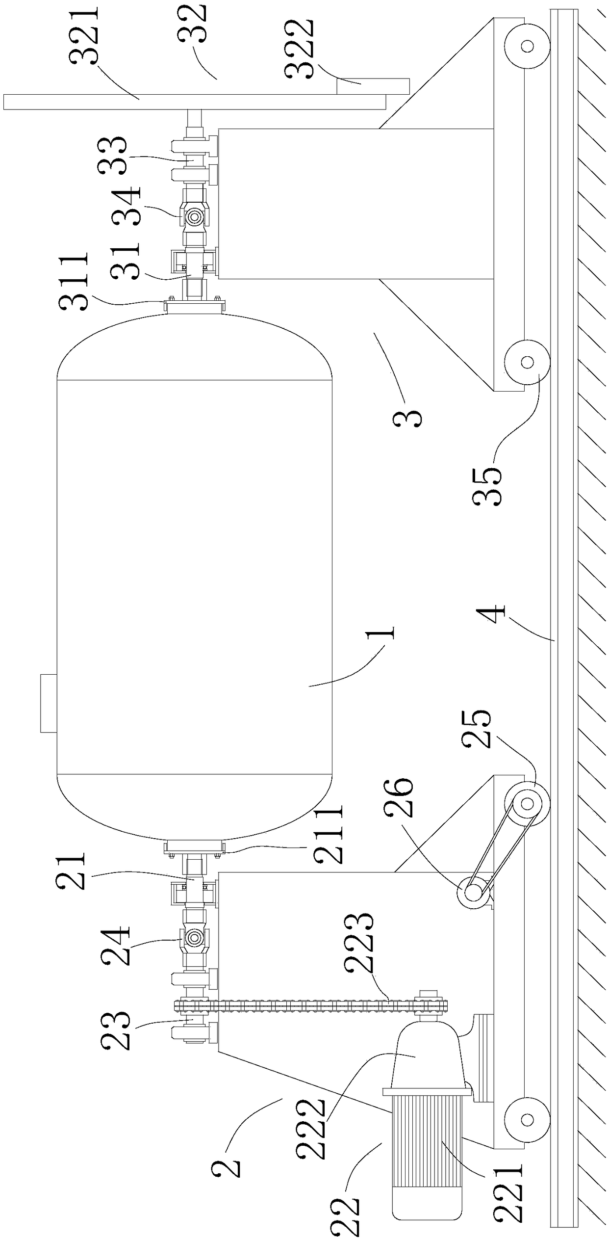
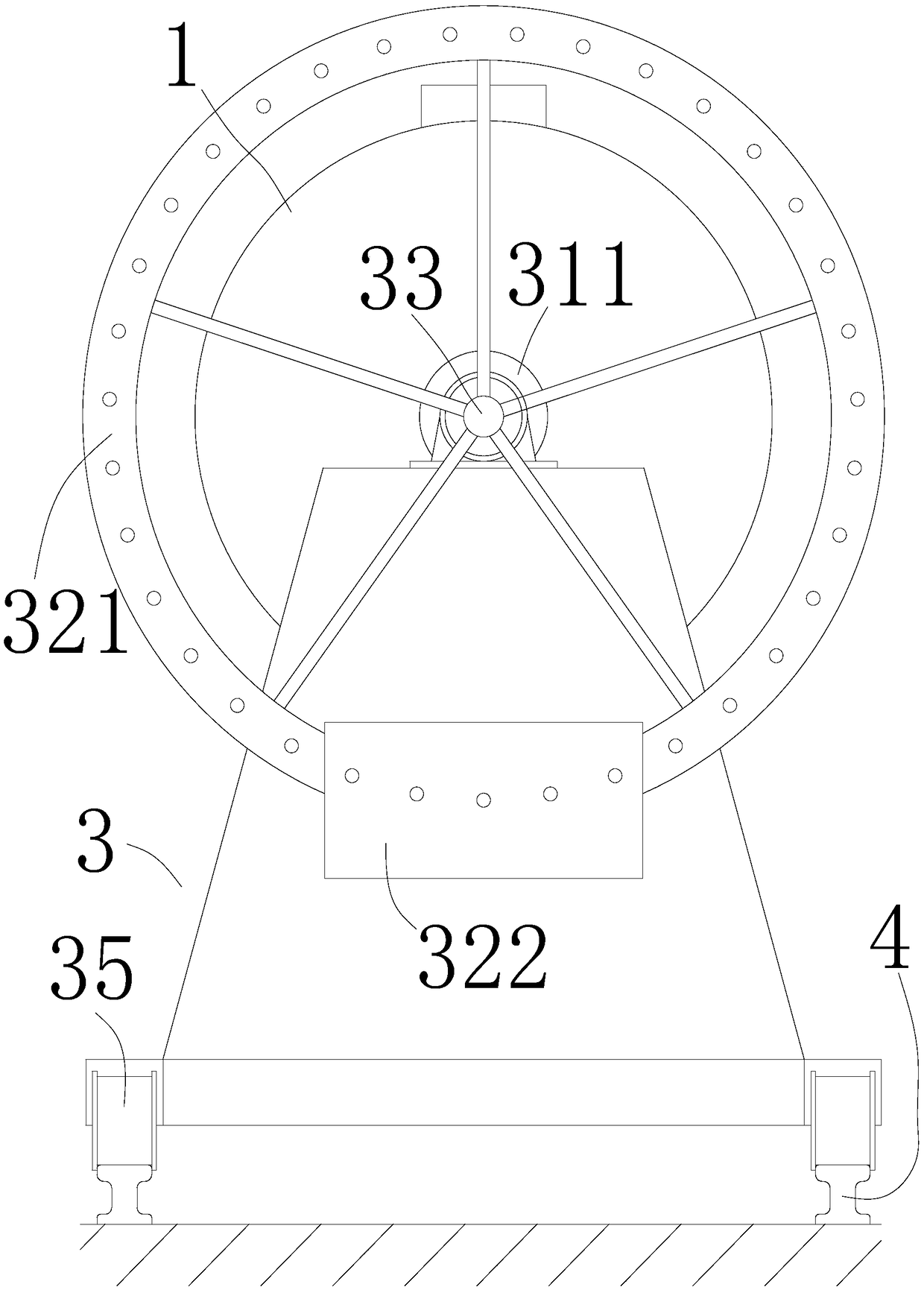
[0030] Such as Figure 1-2 As shown, an oil tank rotary fixture includes a driving frame 2 clamped at the first end of the oil tank 1 and a driven frame 3 clamped at the second end of the oil tank 1 .

[0031] The driving frame 2 is provided with a driving shaft 21 and a driving device 22 for driving the driving shaft 21 to rotate. The second end of the driving shaft 21 is connected with the first end of the oil tank 1 .

[0032] The driven frame 3 is provided with a driven shaft 31 , the first end of the driven shaft 31 is connected to the second end of the oil tank 1 , and the driven shaft 31 is connected to a counterweight device 32 . ...


PUM


Abstract

The invention relates to the field of clamps, in particular to an oil tank rotation clamp. The oil tank rotation clamp comprises a drive frame clamped at the first end of an oil tank, and a driven frame clamped at the second end of the oil tank. The drive frame is provided with a drive shaft and a drive device driving the drive shaft to rotate. The second end of the drive shaft and the first end of the oil tank are connected together. The driven frame is provided with a driven shaft, the first end of the driven shaft is connected with the second end of the oil tank, and the driven shaft is connected to a balance weight device. The oil tank rotation clamp has the beneficial effects that through cooperation of the drive frame and the driven frame, the oil tank is clamped; then the drive device is utilized for conveniently adjusting the position of the oil tank, the oil tank is rotated, and accordingly welding, paint spraying and other operation are conducted; and through the balance weight device, the weight of the oil tank can be distributed more evenly, and accordingly the problem that during oil tank rotation, centrifugal force is generated due to uneven mass distribution of the oil tank, and vibration and instability of the oil tank are caused is solved.

Description

technical field [0001] The invention relates to the field of clamps, in particular to an oil tank rotary clamp. Background technique [0002] Horizontal oil tanks are elongated containers used to store crude oil, vegetable oil, chemical solvents, water or other petroleum products. The horizontal oil tank is composed of an end cover, a horizontal circular or oval tank wall and a saddle, and is usually used in production links or gas stations. The volume of horizontal oil tanks is generally less than 100 cubic meters. It is generally round, oval, and other irregular shapes. Among them, horizontal cylindrical oil tanks are widely used because they can withstand high positive pressure and negative pressure. The ability to reduce pressure is beneficial to reduce the evaporation loss of oil and reduce the risk of fire. It can be manufactured in batches in machinery processing factories, and then transported to the construction site for installation, or installed on the means of ...

Claims


Application Information

Patent Timeline
IPC IPC(8): B23K37/047B23K37/053B05C13/00B05C13/02B05B13/02
CPCB05B13/02B05C13/00B05C13/02B05C13/025B23K37/047B23K37/053B23K37/0533
Inventor 刘学勇
Owner 淮北市向阳锅炉厂
Why Eureka
Try Eureka