Non-contact precise tool setting gauge of ultra-precise diamond turning tool and tool setting method

A diamond tool, ultra-precision technology, applied in the direction of manufacturing tools, metal processing, metal processing equipment, etc., can solve the problems of difficult tool position trimming, poor repeat positioning accuracy, low resolution tools, etc., to avoid tool wear and improve processing The effect of improving precision and improving processing efficiency

Pending Publication Date: 2018-12-07
TIANJIN UNIV OF SCI & TECH
View PDF9 Cites 10 Cited by
  • Summary
  • Abstract
  • Description
  • Claims
  • Application Information

AI Technical Summary

Problems solved by technology

[0006] The present invention aims to improve single-point diamond precision machining accuracy and machining efficiency as the ultimate goal, takes the tool position detection system during machining as the research object, and aims at the problems of poor repeat positioning accuracy and low resolution of the existing vertical micro tool setting system As well as the problems of low tool efficiency and tool wear caused by the trial cutting method, it is proposed to develop a new optical tool online detection device
Based on image recognition technology, the device adopts a new type of ultra-high repeatability positioning accuracy mechanical structure and optical system to realize the automatic acquisition of tool parameters in the ultra-precision machining process, and can calculate and trim tool offsets to meet the requirements of optical free-form surface machining accuracy. Need to solve the problem that the tool position is difficult to trim in ultra-precision machining

Method used


Image

  • Non-contact precise tool setting gauge of ultra-precise diamond turning tool and tool setting method
  • Non-contact precise tool setting gauge of ultra-precise diamond turning tool and tool setting method
  • Non-contact precise tool setting gauge of ultra-precise diamond turning tool and tool setting method

Examples


Embodiment Construction

[0034] The present invention will be further described in detail below in conjunction with the accompanying drawings and through specific embodiments. The following embodiments are only descriptive, not restrictive, and cannot limit the protection scope of the present invention.

[0035] Concrete implementation steps of the present invention are:

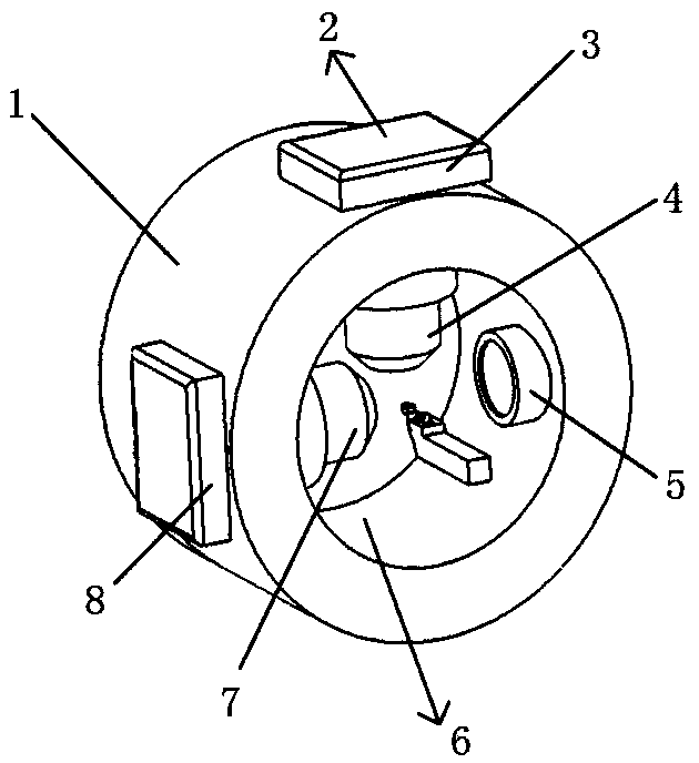
[0036] 1. Structural design of the tool setting instrument (on-line detection system for diamond tools);

[0037] 2. Calculation of microscope lens and CCD parameters;

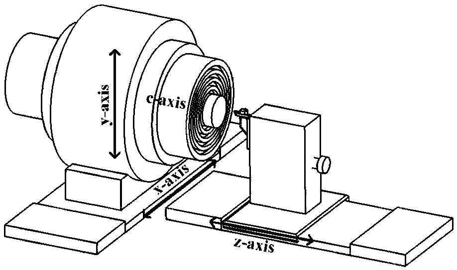
[0038] 3. Adjust the ultra-precise alignment between the arc center of the tool and the center of the spindle;

[0039] 4. Use the optical detection device to obtain the image of the tool, and obtain the parameters of the diamond tool through image processing;

[0040] 5. Establish an error evaluation system for processing path compensation.

[0041] The specific implementation steps of the structural design of the tool setting instrument (diamond cutter on-line ...


PUM


Abstract

The invention relates to a non-contact precise tool setting gauge of an ultra-precise diamond turning tool and a tool setting method. The tool setting gauge comprises a supporting ring body, lenses inthe X direction and the Y direction, CCDs and a lighting source in the X direction. The lens in the X direction and the CCD of the lens in the X direction are arranged at the position, correspondingto the X-axis direction of the lathe coordinates, of the supporting ring body, the lens in the Y direction and the CCD of the lens in the Y direction are arranged at the position, corresponding to theY-axis direction of the lathe coordinates, of the supporting ring body, the lenses in the X direction and the Y direction are located on the inner side of the supporting ring body, the CCDs in the Xdirection and the Y direction are located on the outer side of the supporting ring body, and the lighting source is arranged at the position, facing the lens in the X direction, of the inner side of the supporting ring body. The tool setting gauge and the tool setting method thereof replace a traditional trial cutting method, ultra-precise machining tool high-precision optical online detection isachieved, the problems that an ultra-precise machining tool is long in position adjusting period, and tool wear is hard to avoid are solved, machining efficiency is greatly improved, the tool is freeof wear, and the wide application prospects and the large popularization value are achieved.

Description

technical field [0001] The invention belongs to the field of ultra-precision manufacturing and the field of mechanical parameter measurement, and relates to a non-contact measurement technology for ultra-precision turning diamond tools, in particular to a non-contact precision tool setting instrument and method for ultra-precision turning diamond tools. Background technique [0002] With the acceleration of the pace of life in modern society and the intensification of energy consumption, people hope that instruments and equipment can be more portable and energy-saving. Therefore, modern optoelectronic instruments are developing in the direction of miniaturization, integration and light weight, whether for military or civilian use. The optical components used in traditional optical systems are mainly flat or spherical, and multiple optical components are needed to achieve good optical design requirements. Therefore, the optical system is generally more complicated. With the d...

Claims


Application Information

Patent Timeline
Patent Type & Authority Applications(China)
IPC IPC(8): B23Q17/24B23Q15/22
CPCB23Q15/22B23Q17/2428
Inventor 程颖李晓凡卢永斌
Owner TIANJIN UNIV OF SCI & TECH
Why Eureka
Try Eureka