Prefabricating method for UHPC small box beam end diaphragm

A technology of small box girders and diaphragms, applied to bridges, manufacturing tools, bridge materials, etc., can solve the problems of large amount of construction work on site, unfavorable rapid construction, easy damage of horizontal connections, etc., and achieve the effect of improving prefabrication efficiency

Inactive Publication Date: 2018-12-07
GUANGZHOU MUNICIPAL ENG DESIGN & RES INST CO LTD
View PDF11 Cites 2 Cited by
  • Summary
  • Abstract
  • Description
  • Claims
  • Application Information

AI Technical Summary

Problems solved by technology

[0003] Although there are various types of prefabricated bridges, they all have their own shortcomings: the steel structure has a large amount of on-site welding (bolts), and the steel bridge deck has fatigue cracking problems; the steel-concrete composite structure has a large self-weight, and the bridge deck can only partially Prefabrication, large amount of on-site pouring; prestressed reinforced concrete structure is heavy, the horizontal connection is easy to be damaged, and there are many durability diseases
UHPC materials have been greatly developed in the field of bridges in countries such as France and Malaysia, but in my country, their theoretical research is mostly concentrated in the three forms of T-beam, wide box girder and π-beam, and the research on UHPC small box girder is basically It is blank, but the T-beam structure has many horizontal connections, and there are many joints on site, which is not conducive to rapid construction; the wide box girder realizes prefabricated construction through the longitudinal division of the box girder, and the on-site construction work is heavy and complicated; the π-beam There are only longitudinal joints on the bridge deck, which is convenient for on-site construction, and the prestressing force is cancelled, which avoids the difference in the anti-arching of the main girder caused by the prestressing tension, thereby ensuring the quality of the transverse joints and reducing the thickness of the bridge deck pavement. Lack of prestress leads to bridge span limitation

Method used


Image

  • Prefabricating method for UHPC small box beam end diaphragm
  • Prefabricating method for UHPC small box beam end diaphragm
  • Prefabricating method for UHPC small box beam end diaphragm

Examples


Embodiment Construction

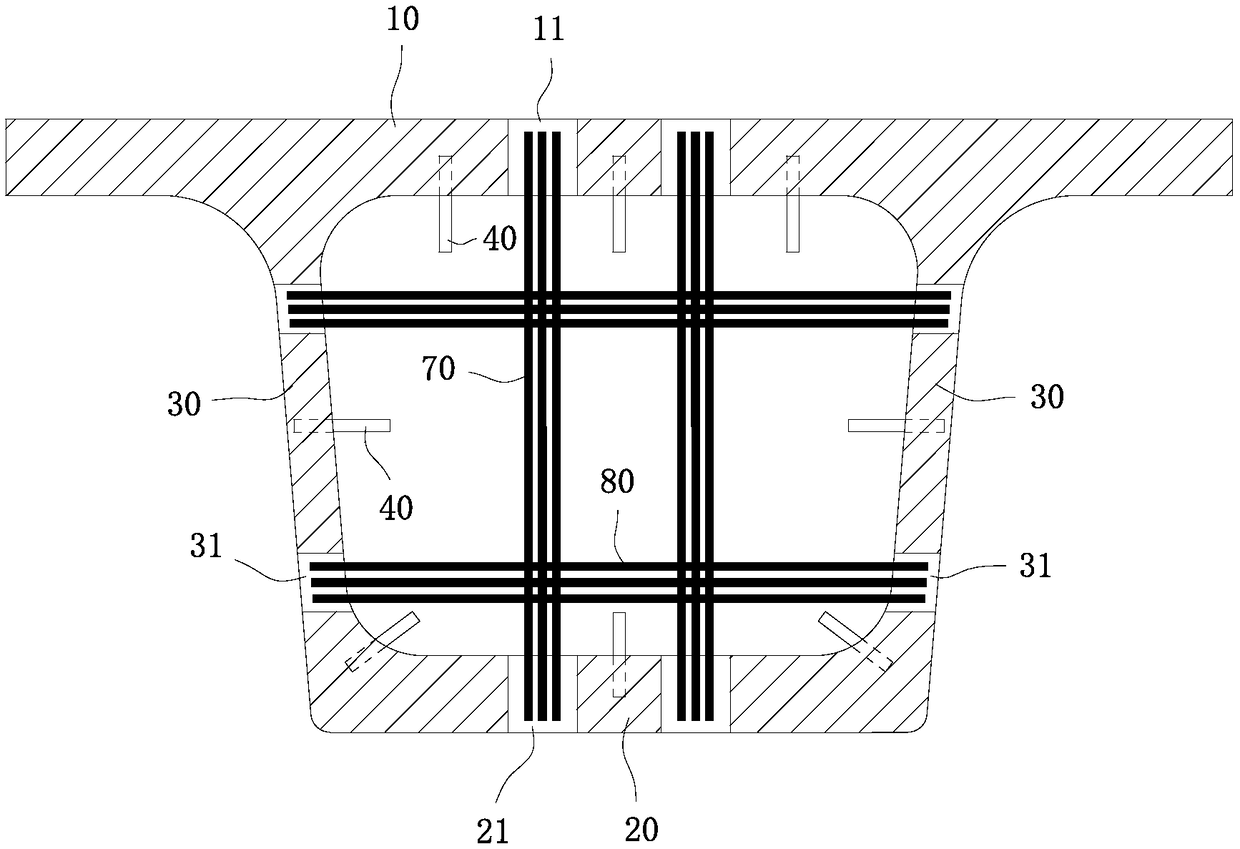
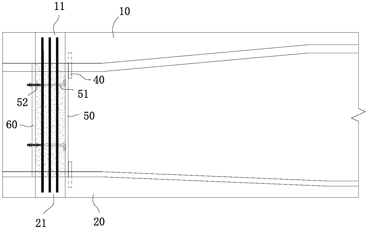
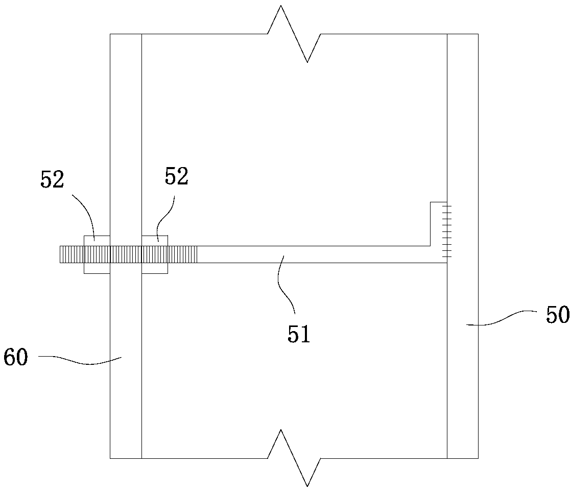
[0023] refer to Figure 1 to Figure 3 , the prefabrication method of UHPC small box girder end diaphragm of the present invention, comprises the following steps:

[0024] S1. Prefabricate the box girder body consisting of top plate 10, bottom plate 20 and web 30 by pouring ultra-high performance concrete through the outer formwork and inner formwork, and the top plate 10, bottom plate 20 and web plate at the same cross-sectional position at the end of the box girder body 30 are respectively reserved with a top plate reserved hole 11, a bottom plate reserved hole 21 and a web reserved hole 31. The alignment between the top plate reserved hole 11 and the bottom plate reserved hole 21 is in the same vertical direction. The plate reserved holes 31 are also aligned in the same horizontal direction. The slow bonded prestressed tendons are pre-embedded in the bottom plate 20 and web 30 of the box girder body along the longitudinal direction, and the mid-span intervals are predetermin...


PUM


Abstract

The invention discloses a prefabricating method for a UHPC small box beam end diaphragm. A box beam body is prefabricated by adopting ultra-high-performance concrete, the diaphragm is prefabricated atthe end of the box beam body after the box beam body reaches the preset strength, a cast-in-situ material of the diaphragm adopts ultra-high-performance concrete or common concrete, retard-bonded prestressed tendon tensioning operation is conducted after the diaphragm reaches the preset strength, and finally high-pressure steam curing is conducted on the whole box beam body. The prefabricated boxbeam body is adopted and cooperates with post-poured UHPC or common concrete to form the diaphragm, the cast-in-situ end partition and the prefabricated UHPC box beam body can be effectively connected into a whole, the thickness of the diaphragm can be selectively adjusted according to the pouring concrete material, the prefabricating efficiency of the UHPC small box beam end diaphragm is effectively improved, and the prefabricating method is more suitable for bridge industry assembly line production.

Description

technical field [0001] The invention relates to the technical field of bridge engineering structures, in particular to a prefabrication method for a diaphragm at the end of a UHPC small box girder. Background technique [0002] In recent years, my country has actively explored and enriched green bridge construction methods with high speed, low road interference and quietness, vigorously advocated prefabricated construction of bridges, and actively explored the application of new materials in prefabricated bridges, and built a large number of representative bridges. The prefabricated bridges, industrialized production and prefabricated construction of bridges have become a major trend. [0003] Although there are various types of prefabricated bridges, they all have their own shortcomings: the steel structure has a large amount of on-site welding (bolts), and the steel bridge deck has fatigue cracking problems; the steel-concrete composite structure has a large self-weight, an...

Claims


Application Information

Patent Timeline
Patent Type & Authority Applications(China)
IPC IPC(8): B28B23/04B28B23/02B28B23/00B28B7/00B28B7/02E01D2/04E01D101/28
CPCB28B7/0002B28B7/0029B28B7/02B28B23/00B28B23/02B28B23/04E01D2/04E01D2101/28
Inventor 宁平华彭聪王晟唐明裴邓德伦郭钰瑜王如寒麦梓浩欧键灵熊正元杨勇
Owner GUANGZHOU MUNICIPAL ENG DESIGN & RES INST CO LTD
Why Eureka
Try Eureka