Electromagnetic suspension power generation train system

An electromagnetic levitation and train technology, applied in sliding/floating railway systems, electric vehicles, tunnel systems, etc., can solve the problems of low input-output ratio, large electrical dependence, large electromagnetic radiation, etc. Ensuring safety and comfort, reducing impact and friction

Inactive Publication Date: 2018-12-07
邱洪武
View PDF1 Cites 7 Cited by
  • Summary
  • Abstract
  • Description
  • Claims
  • Application Information

AI Technical Summary

Problems solved by technology

[0002] High-speed rail and maglev trains are the most influential public high-speed vehicles today. They are not only fast but also relatively safe. However, their speed increases are affected by both air resistance and wheel-rail friction. The potential has almost reached the limit, and the construction and operation costs Expensive, single function, long payback period, low input-output ratio, difficult to recover investment
Wherever the high-speed rail goes, the electricity goes first, and long-distance high-voltage lines need to be laid, which requires a huge investment. However, the maglev train not only has a small capacity and high cost, but also relies heavily on electricity. Its magnetic field is strong, and the magnetic field is exposed outside the train. , lack of electromagnetic field shielding protection, electromagnetic radiation is very large, it is difficult to promote, and the speed of maglev is also seriously affected by air resistance

Method used


Image

  • Electromagnetic suspension power generation train system
  • Electromagnetic suspension power generation train system
  • Electromagnetic suspension power generation train system

Examples


Embodiment Construction

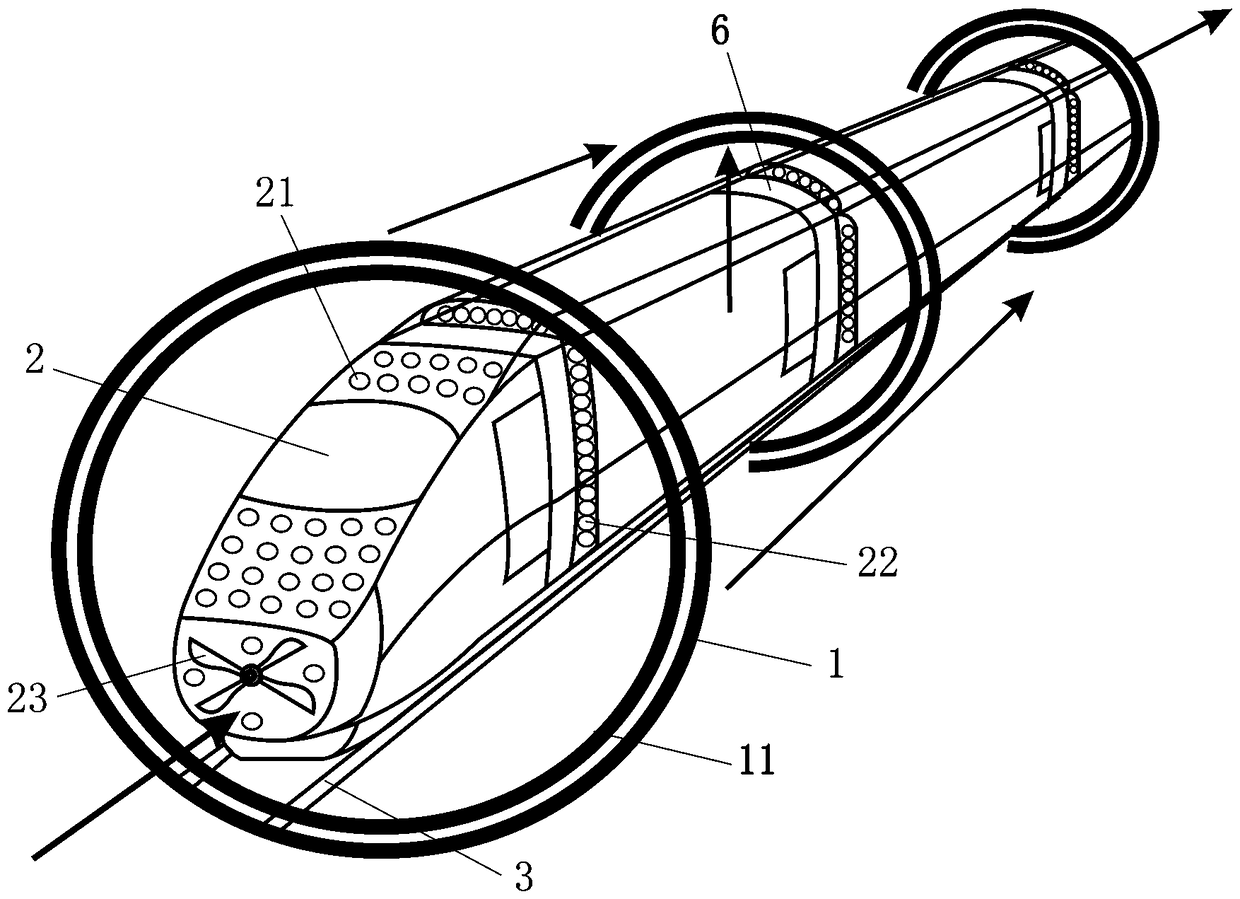
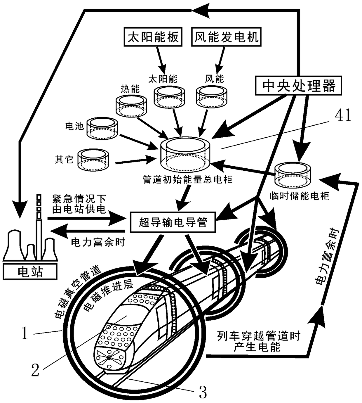
[0034] Such as figure 1 As shown, the electromagnetic levitation power generation train system proposed by the present invention includes: a pipeline 1 , a train 2 inside the pipeline 1 , and a plurality of tracks 3 arranged between the pipeline 1 and the train 2 . Each track 3 includes two rails installed on the inner wall of the pipeline 1, and an outer suspension electromagnet is arranged between the two rails. The body of the train 2 is provided with rails running along the track 3. The rails include two Wheel rails, an inner suspension electromagnet opposite to the outer suspension electromagnet is arranged between the two wheel rails. Such as figure 2 Shown is a schematic diagram of the train power supply relationship in the present invention. The solar and wind energy devices along the railway, as well as the electric energy generated when the train passes through the electromagnetic vacuum pipeline, can supply power for the train 2, and the surplus electric energy c...


PUM


Abstract

The invention discloses an electromagnetic suspension power generation train system which comprises a pipeline, a train located in the pipeline and multiple tracks arranged between the pipeline and the train. Each track comprises two rails. Outer suspension electromagnets are distributed between every two rails. A train body of the train is provided with a train track running along the corresponding track. The train track comprises two wheel rails. Inner suspension electromagnets opposite to the outer suspension electromagnets in position are distributed between the two wheel rails. The polarity of the powered-on inner suspension electromagnets is the same as that of the outer suspension electromagnets. The multiple tracks are arranged at intervals around the train. The train is limited bythe multiple tracks to be suspended right in the center of the pipeline. When the train penetrates through the electromagnetic vacuum pipeline, an inner electromagnetic propelling layer on the outerwall of the train magnetically repels an outer electromagnetic propelling layer on the inner wall of the pipeline through the same polarity, an outer electromagnetic propelling layer of the inner wallof a power generation closed traverse cutting pipeline arranged on the train obtains electric energy, a power generation function is achieved, energy such as solar energy and wind energy along a railway can further be used for providing sufficient power for the train, and operation cost is reduced.

Description

technical field [0001] The invention relates to the technical field of electromagnetic levitation trains, and more specifically, relates to an electromagnetic levitation power generation train system. Background technique [0002] High-speed rail and maglev trains are the most influential public high-speed vehicles today. They are not only fast but also relatively safe. However, their speed increases are affected by both air resistance and wheel-rail friction. The potential has almost reached the limit, and the construction and operation costs High cost, single function, long payback period, low input-output ratio, difficult to recover investment. Wherever the high-speed rail goes, the electricity goes first, and long-distance high-voltage lines need to be laid, which requires a huge investment. However, the maglev train not only has a small capacity and high cost, but also relies heavily on electricity. Its magnetic field is strong, and the magnetic field is exposed outside...

Claims


Application Information

Patent Timeline
Patent Type & Authority Applications(China)
IPC IPC(8): B61B13/10B61B13/08B60L13/04B60L13/10
CPCB60L13/04B60L13/10B60L2200/26B61B13/08B61B13/10Y02T30/00
Inventor 邱洪武
Owner 邱洪武
Why Eureka
Try Eureka