Efficient biogas digester for removing slag

A biogas digester and high-efficiency technology, applied in biochemical cleaning devices, gas production bioreactors, bioreactors/fermenters for specific purposes, etc., can solve problems such as low efficiency of biogas generation and troublesome cleaning of biogas residues, and achieve reduction Effects of resistance, reduction of energy loss, and improvement of activity

Inactive Publication Date: 2018-12-07
广东锐拓环境科技有限公司
View PDF6 Cites 4 Cited by
  • Summary
  • Abstract
  • Description
  • Claims
  • Application Information

AI Technical Summary

Problems solved by technology

However, during the use of existing biogas digesters, due to insufficient contact between raw materials and bacterial materials and the influence of fermentation environment temperature, the efficiency of biogas generation is low, and the cleaning of biogas residues in the later stage is also troublesome.

Method used


Image

  • Efficient biogas digester for removing slag
  • Efficient biogas digester for removing slag
  • Efficient biogas digester for removing slag

Examples


Embodiment 1

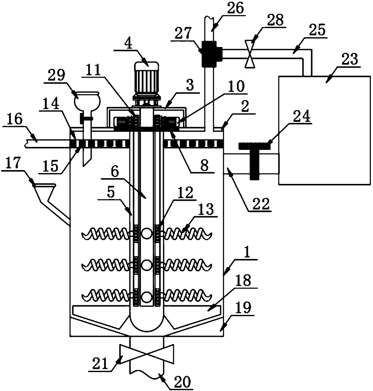
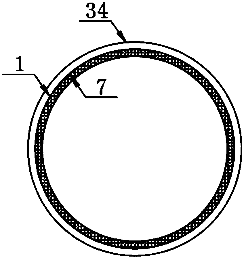
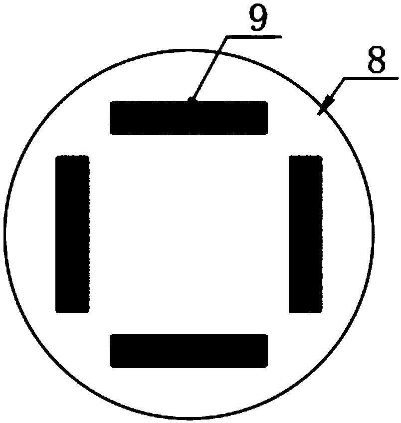
[0028] The present invention provides such Figure 1-6 A high-efficiency biogas digester that is convenient for slag removal is shown, comprising an anaerobic fermentation tank 1, a tank cover 2 is provided on the top of the anaerobic fermentation tank 1, and a mounting frame 3 is arranged on the top of the tank cover 2. The installation One side of the rack 3 is provided with a bacteria hopper 29 and the other side is provided with a second exhaust pipe 26, and the drop pipe of the bacteria hopper 29 and the second exhaust pipe 26 are all connected to the anaerobic fermentation tank 1. The installation The top of the frame 3 is provided with a positive and negative motor 4, and the tank cover 2 is embedded with a disk 8, the output shaft of the positive and negative motor 4 is connected to the disk 8, and the bottom of the disk 8 is provided with an outer shaft 5, Stirring blades 18 are provided on the circumferential side surface of the bottom end of the outer shaft 5, and a...

Embodiment 2

[0035] Further, in the above technical solution, one side of the stirring blade 18 is set as a plane and the other side is set as a raised arc surface, and the arc surface is tapered outwardly, which can greatly reduce the rotation speed of the stirring blade 18. The resistance of the mixture received during the process, thereby reducing the energy loss of the forward and reverse motor 4 when it works.

[0036] Further, in the above technical solution, the bottom of the anaerobic fermentation tank 1 is provided with a wedge-shaped platform 19, and the top of the wedge-shaped platform 19 is set as a downward inclined surface, and the bottom end of the inclined surface is matched with the slag discharge pipe 20 , can be used to guide the discharge of biogas residues, avoid residues of biogas residues at the corners inside the anaerobic fermentation tank 1 and increase the difficulty of cleaning biogas residues.

[0037] Further, in the above technical solution, the connecting pi...


PUM


Abstract

The invention discloses an efficient biogas digester for removing slag. The efficient biogas digester comprises an anaerobic fermentation tank; a tank cover is arranged at and matched with the top ofthe anaerobic fermentation tank; a mounting rack is arranged on the top of the tank cover; a bacteria hopper is arranged on one side of the mounting rack while a second exhaust pipe is arranged on theother side; a blanking pipe of the bacteria hopper and the second exhaust pipe are both communicated with the anaerobic fermentation tank; a positive and negative motor is arranged on the top of themounting rack; a disc is embedded on the tank cover; an output shaft of the positive and negative motor is in driving connection with the disc; an external shaft is arranged on the bottom of the disc.The efficient biogas digester for removing slag utilizes a stirring blade and a stirring rod to simultaneously mix the raw materials and bacteria in the anaerobic fermentation tank in the manner of dual overlapping stirring, so that the mixture can be more quickly and uniformly mixed. In the mixing process, a heating pipe and a heating wire are adopted for generating heat, so as to increase the temperature in the anaerobic fermentation tank, promote the activity of strains and accelerate the generation of methane.

Description

technical field [0001] The invention relates to the field of biogas production equipment, in particular to a high-efficiency biogas digester which is convenient for slag removal. Background technique [0002] As we all know, biogas is an energy-saving, environmentally friendly and economical green energy, which is widely favored. The production of biogas can deal with domestic waste, which is energy-saving and environmentally friendly. Biogas residue and biogas slurry can be used as green fertilizers for farmland fertilization, which can reduce chemical fertilizers. The usage amount can produce green organic vegetables and food. However, during the use of the existing biogas digesters, due to insufficient contact between the raw material and the bacterial material and the influence of the temperature of the fermentation environment, the biogas production efficiency is low, and the cleaning of the biogas residue in the later stage is also troublesome. [0003] Therefore, it ...

Claims


Application Information

Patent Timeline
Patent Type & Authority Applications(China)
IPC IPC(8): C12M1/107C12M1/02
CPCC12M21/04C12M23/02C12M23/36C12M23/38C12M27/02C12M39/00C12M41/12C12M41/22C12M41/24
Inventor 高新金刘付六平陈忠平陈佩文简明扬何志成撖学山邹国营
Owner 广东锐拓环境科技有限公司
Why Eureka
Try Eureka