Energy dissipation body structure of elevated single-column station

A shock-absorbing body and energy-dissipating technology, applied in special structures, earthquake-proof, building components, etc., can solve the problems of difficult maintenance and replacement, affecting the seismic performance of structural systems, occupying the usable area of ​​the structure, etc., so as to improve safety. Redundancy, improved torsional effect, reduced repair cost effect

Pending Publication Date: 2018-12-07
TSINGHUA UNIV
View PDF0 Cites 7 Cited by
  • Summary
  • Abstract
  • Description
  • Claims
  • Application Information

AI Technical Summary

Problems solved by technology

This design method relies heavily on the deformation capacity and hysteretic energy dissipation characteristics of the main structural members after entering the elastic-plastic stage, and is a passive anti-seismic countermeasure: in order to ensure the energy dissipation capacity of the plastic hinge area, it is often necessary to increase the cross-section of the member or increase the Cross-section reinforcement, which not only consumes building materials and occupies the usable area of ​​the structure, but also increases the structural quality and stiffness may also lead to the enhancement of earthquake action, and does not have the ability to actively adjust
Once these key main structures that store and consume seismic energy input are damaged or destroyed under strong earthquakes, the overall seismic performance of the structural system will be seriously affected, and the high difficulty of its maintenance and replacement is not easy to meet the requirements proposed in the field of earthquake resistance and disaster reduction in recent years. Structural performance requirements for "post-earthquake functional restorability"

Method used


Image

  • Energy dissipation body structure of elevated single-column station
  • Energy dissipation body structure of elevated single-column station
  • Energy dissipation body structure of elevated single-column station

Examples


Embodiment 1

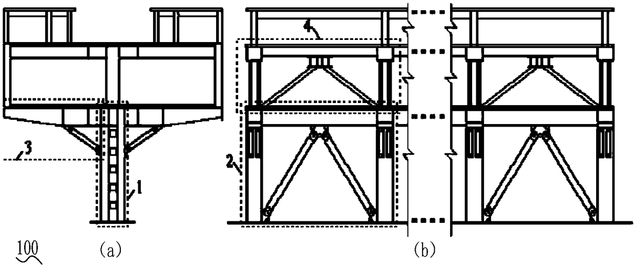
[0048] Such as figure 2 As shown, it is used for the energy dissipation and shock absorption system of the elevated single-pillar station. The system mainly includes four types of energy dissipation and shock absorption substructures, 1-4 are energy dissipation pier columns, bottom buckling-resistant bracing frame, and axillary buckling-resistant bracing cantilever conversion Beams and second-story shear-coupled eccentrically braced frames. In the elevated single-pillar station, according to the different seismic fortification intensity and fortification goals of the site where the project is located, one or more energy-dissipating and shock-absorbing substructures can be selected as required to form the energy-dissipating and shock-absorbing system of the station, and for a certain An arrangement of energy-dissipating and shock-absorbing substructures can be used individually or repeatedly in one or more places of the structure according to requirements. In these substructu...

Embodiment 2

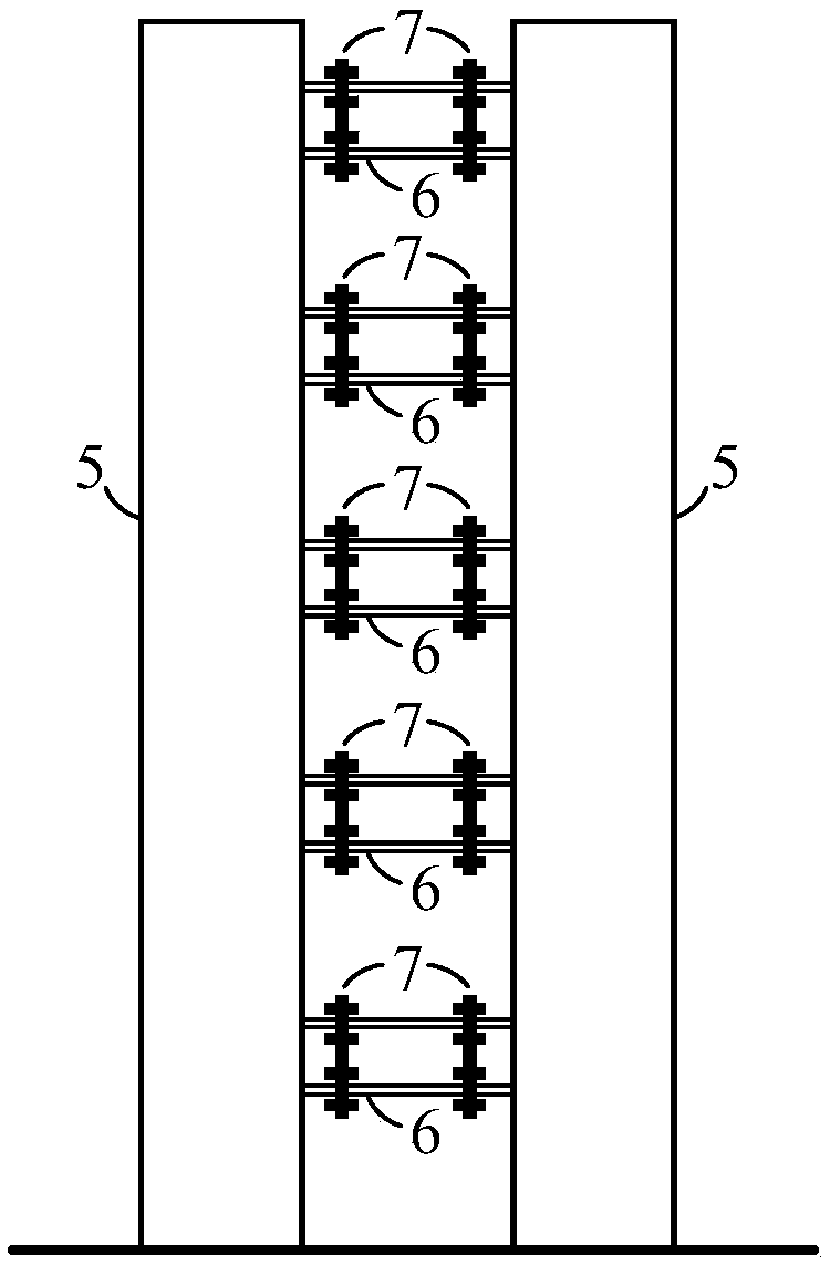
[0050] Such as image 3 As shown, the energy dissipation and shock absorption system used for the elevated single-column station, for the energy-dissipating pier column structure it contains. The energy-dissipating pier column is mainly used to improve the seismic performance of the structure in the transverse bridge direction. The energy-dissipating pier column is composed of two tightly arranged steel tube concrete column limbs, and is connected by a low yield point shear coupling beam in the middle. The corbels are welded on the inner side of the steel tube concrete column limbs during processing, and the shear coupling beam passes through such as Figure 7 Connection nodes shown are connected to steel corbels. Compared with the original single-column pier, the width and cross-sectional area of ​​the energy-dissipating pier column are increased, so the stiffness and bearing capacity in the elastic state are increased, which can effectively control the lateral deformation o...

Embodiment 3

[0052] Such as Figure 4 As shown in , the energy dissipation and shock absorption system used for the elevated single-column station is for the underlying buckling-resistant bracing frame substructure contained in it. The buckling-resistant bracing frame is mainly used to improve the seismic performance of the structure along the bridge to the ground floor. The buckling-resistant bracing frame is composed of the column limbs of the pier columns on the ground floor and the longitudinal main beam of the first floor, and the buckling-resistant bracing connection is set in the middle. After the frame construction is completed, the hinged joints are welded at the parts connected to the anti-buckling supports. One end of the hinged joints is welded to the frame. When passing through, attention should be paid to the use of reinforcement plates for reinforcement, while the other end of the hinged joints is still designed as an end plate connection. form, thereby employing buckling-re...


PUM


Abstract

The invention discloses an energy dissipation body structure of an elevated single-column station. The energy dissipation body structure comprises energy dissipation pier studs, a bottom layer anti-buckling supporting frame, in-axillary additional anti-buckling supporting cantilever transfer girders and a two-layer shearing coupling beam eccentric supporting frame which are all used for providingadditional rigidity when the earthquake magnitude is smaller than or equal to the preset earthquake magnitude and enter a yield state from an elastic state to plastically deform so as to consume partof input energy of an earthquake independently or in freedom cooperation with one another when the earthquake magnitude is larger than the preset earthquake magnitude. The energy dissipation body structure is suitable for the elevated single-column station; for the same type of irregular structure, some energy dissipation sub-structure in the energy dissipation body structure can also be adopted in the similar anti-seismic weak link, and therefore the anti-seismic performance and after-disaster restorability of the energy dissipation body structure are improved, and the energy dissipation bodystructure has good popularization prospects.

Description

technical field [0001] The invention relates to the technical field of structural engineering, in particular to an energy-dissipating and shock-absorbing structure of an elevated single-column station. Background technique [0002] Such as figure 1 As shown, in order not to affect the existing urban road traffic, the elevated platform is usually set up at the isolation belt in the middle of the road. The lower bridge structure adopts the form of a single column in the middle of the road in the longitudinal direction, and the pier columns extend out cantilevered cover beams along both sides to serve as the station building. The support system of the building structure, generally the first floor cover beam supports the station hall floor, the upper floor cover beam supports the platform floor, and the station as a whole forms a single-column long cantilever structure system in the shape of a "dry". Although this type of structure can efficiently utilize the urban building spa...

Claims


Application Information

Patent Timeline
Patent Type & Authority Applications(China)
IPC IPC(8): E04H9/02E04B1/34E04B1/98
CPCE04H9/02E04B1/3412
Inventor 许立言聂建国庄亮东
Owner TSINGHUA UNIV
Why Eureka
Try Eureka