Visual measuring device and measuring method for curved plate-rotor gap of air pre-heater

A technology of air preheater and measuring device, which is applied in the direction of measuring device, optical device, instrument, etc., can solve the problems of unmeasurable adjustment of the gap between the arc plate and the rotor, overload of the air preheater drive motor, invisible, etc. The measurement effect is stable for a long time, the operation efficiency is improved, and the effect of convenient and precise adjustment

Inactive Publication Date: 2018-12-07
XIAN UNIV OF TECH
View PDF8 Cites 6 Cited by
  • Summary
  • Abstract
  • Description
  • Claims
  • Application Information

AI Technical Summary

Problems solved by technology

[0003] The purpose of the present invention is to provide a visual measuring device and measurement method for the gap between the arc-shaped plate and the rotor of the air preheater, so as to solve the problem that the gap between the arc-shaped plate and the rotor in the prior art cannot be measured and cannot be seen, and the gap size is caused by purely relying on experience. Even in the hot state, due to the mushroom-shaped deformation of the rotor due to heating, the fan-shaped plate cannot be lowered in place, causing excessive air leakage, which greatly reduces the working efficiency of the unit, or the rotor and the arc-shaped plate are stuck, the air preheater drive motor is overloaded, and the unit trips. Problems that seriously affect the safety and working efficiency of the unit

Method used


Image

  • Visual measuring device and measuring method for curved plate-rotor gap of air pre-heater
  • Visual measuring device and measuring method for curved plate-rotor gap of air pre-heater
  • Visual measuring device and measuring method for curved plate-rotor gap of air pre-heater

Examples


Embodiment Construction

[0039] The present invention will be further elaborated below in conjunction with the accompanying drawings and specific embodiments.

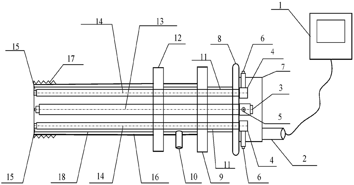
[0040] like figure 1 As shown, the visual measurement device for the air preheater arc plate and the rotor gap includes a video acquisition unit and a supplementary light mechanism arranged on the installation body; the video acquisition unit and supplementary light mechanism include a camera 3 installed on the outside of the equipment mounting seat 8 And the two-line laser light source 4, and the extension lens 13 and the two-line laser pipeline 11 and the word laser head 15 installed on the inside of the equipment mounting seat 8; The line laser pipeline 11 and the one-word laser head 15 are connected to each other; the inner cavity of the double-line laser pipeline 11 is the laser optical path 14, and the double-line laser pipeline 11 and the extended lens 13 are made as an integrated three-hole pipeline parallel to the axis line The struc...


PUM


Abstract

The invention discloses a visual measuring device and measuring method for a curved plate-rotor gap of an air pre-heater. The visual measuring device comprises a video collecting unit and a light supplementing mechanism that are arranged on a mounting body. In addition, the visual measuring method includes: each visual measuring device is calibrated before usage and a correspondence relationship between a displacement increment and a pixel increment is found out; during the application process, the visual measuring devices are installed, a camera is used for acquiring a dual-line laser image of a target area and transmits the image to an image processor, the image processor feeds back a gap value obtained by processing to a video monitoring unit, and the gap value is monitored in real time; and when the gap value exceeds a normal range, the system carries out alarming automatically for warning, so that the operator is able to adjust the arc plate position timely based on the monitoringpicture. According to the invention, the gap picture and the gap size information can be observed in real time and thus the operator can adjust the gap between the arc plate and the side of the rotorof the air pre-heater conveniently, so that the operating efficiency of the set is improved and the maintenance and replacement become convenient.

Description

technical field [0001] The invention belongs to the technical field of video monitoring and visual measurement, and is used for the visual measurement of object gaps under parallel line laser irradiation. In particular, the invention relates to a visual measurement device and a measurement method for the gap between an arc plate of an air preheater and a rotor. Background technique [0002] The "rotary air preheater" in thermal power units is one of the main auxiliary machines of large industrial boilers, referred to as "air preheater". When the air preheater is working, the "mushroom" deformation will occur due to the uneven heating of the upper and lower sides, and the deformation is constantly changing with the different working loads of the boiler, that is, the gap between the arc plate of the air preheater and the rotor is a change quantity. The existence of the gap will cause a large amount of hot air to leak into the flue, which will increase the power consumption o...

Claims


Application Information

Patent Timeline
Patent Type & Authority Applications(China)
IPC IPC(8): G01B11/14
CPCG01B11/14
Inventor 杨延西田瑞明邓毅李听团宋念龙
Owner XIAN UNIV OF TECH
Why Eureka
Try Eureka