Laser source and laser projector

A laser light source and laser beam technology, applied in the optical field, can solve the problems of limited light-receiving area, damage to the fiber coating, low light resistance power density, etc. cooling effect

Active Publication Date: 2018-12-07
QINGDAO HISENSE LASER DISPLAY CO LTD
View PDF7 Cites 5 Cited by
  • Summary
  • Abstract
  • Description
  • Claims
  • Application Information

AI Technical Summary

Problems solved by technology

Due to the large output power of visible light semiconductor lasers, and the end face of the coupling fiber is usually only on the order of hundreds of microns, the light receiving area is extremely limited, and the small position shift of the converging point of the incident beam by the coupling focusing lens will lead to high converging The high-power laser beam irradiates the cladding layer, which causes damage to the fiber cladding layer due to its low light resistance power density

Method used


Image

  • Laser source and laser projector
  • Laser source and laser projector
  • Laser source and laser projector

Examples


Embodiment Construction

[0032] The laser light source and the laser projector provided by the embodiments of the present application are provided with a protective plate. Based on the protective plate, when the laser spot is shifted, the coupling fiber can be prevented from being irradiated by the offset laser spot caused by the cladding layer on the end face of the coupling fiber. damage.

[0033] The embodiments of the present application will be described in detail below with reference to the accompanying drawings, taking a laser light source applied to a laser projector as an example.

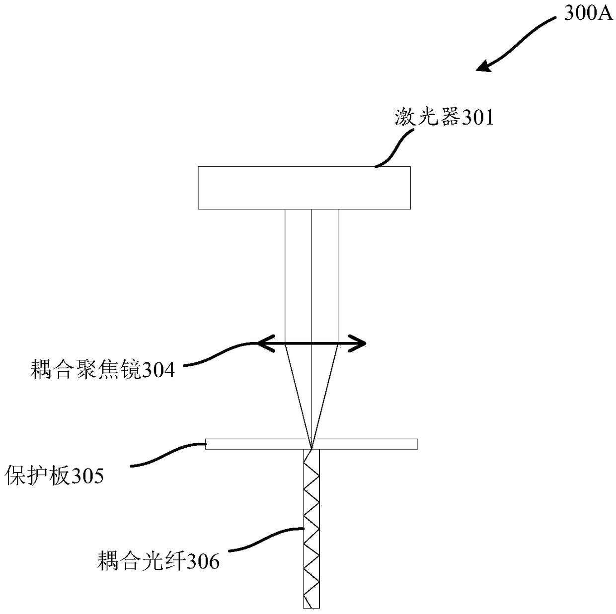
[0034] see Figure 3A and Figure 3B , respectively, are schematic structural diagrams of the laser light sources provided in the embodiments of the present application.

[0035] like Figure 3A As shown, the laser light source 300A includes a laser 301 , a coupling focusing mirror 304 and a protective plate 305 sequentially arranged on the laser light path emitted by the laser 301 . The protective plate 305 i...


PUM


Abstract

The present application discloses a laser source and a laser projector. The laser source includes a laser, a coupled focusing lens disposed in the optical path of a laser beam emitted by the laser, and a protective plate made of a thin metal plate. The protective plate is provided with a through hole at a position corresponding to the end face of a coupling fiber. The diameter of the through holeis between the diameter of a laser spot focused by the coupled focusing lens and the inner diameter of the cladding layer of the coupling fiber. The laser beam emitted by the laser is emitted to the coupled focusing lens, the coupled focusing lens focuses the incident laser beam, and the focused laser beam is emitted to the end face of the coupling fiber through the through hole on the protectiveplate.

Description

technical field [0001] The present application relates to the field of optical technology, and in particular, to a laser light source and a laser projector. Background technique [0002] The schematic diagram of the three-color laser projector is as follows figure 1 shown. Among them, the laser light emitted by the semiconductor lasers (blue DLP, green DLP and red DLP) enters the optical machine after beam expansion, shimming, decoherence, etc. The optical machine modulates the incident beam and outputs it to the projection lens, and finally in the Projected onto the screen to form a projected image. [0003] At present, for laser projectors, in order to achieve high brightness output, compact size and easy installation, an ultra-short focal design is usually adopted to achieve high brightness output of three-primary laser projection, which puts forward higher requirements for the heat dissipation of semiconductor lasers. requirements, especially for red semiconductor las...

Claims


Application Information

Patent Timeline
Patent Type & Authority Applications(China)
IPC IPC(8): G03B21/20
CPCG03B21/2033G03B21/2066
Inventor 郭汝海
Owner QINGDAO HISENSE LASER DISPLAY CO LTD
Why Eureka
Try Eureka