Eureka AIR delivers breakthrough ideas for toughest innovation challenges, trusted by R&D personnel around the world.

Preventing electrical breakdown

An electromechanical and housing technology, applied in the direction of electromechanical devices, electrical components, electric components, etc.

Pending Publication Date: 2018-12-07
ROLLS ROYCE PLC
View PDF6 Cites 0 Cited by
  • Summary
  • Abstract
  • Description
  • Claims
  • Application Information

AI Technical Summary

Problems solved by technology

Due to the thrust demands on the propulsion system and the necessary high voltage demands of the electric motors in such applications, the problem may not be resolved by simply transitioning to a voltage state that does not exceed the breakdown voltage

Method used


Image

  • Preventing electrical breakdown
  • Preventing electrical breakdown
  • Preventing electrical breakdown

Examples


Embodiment Construction

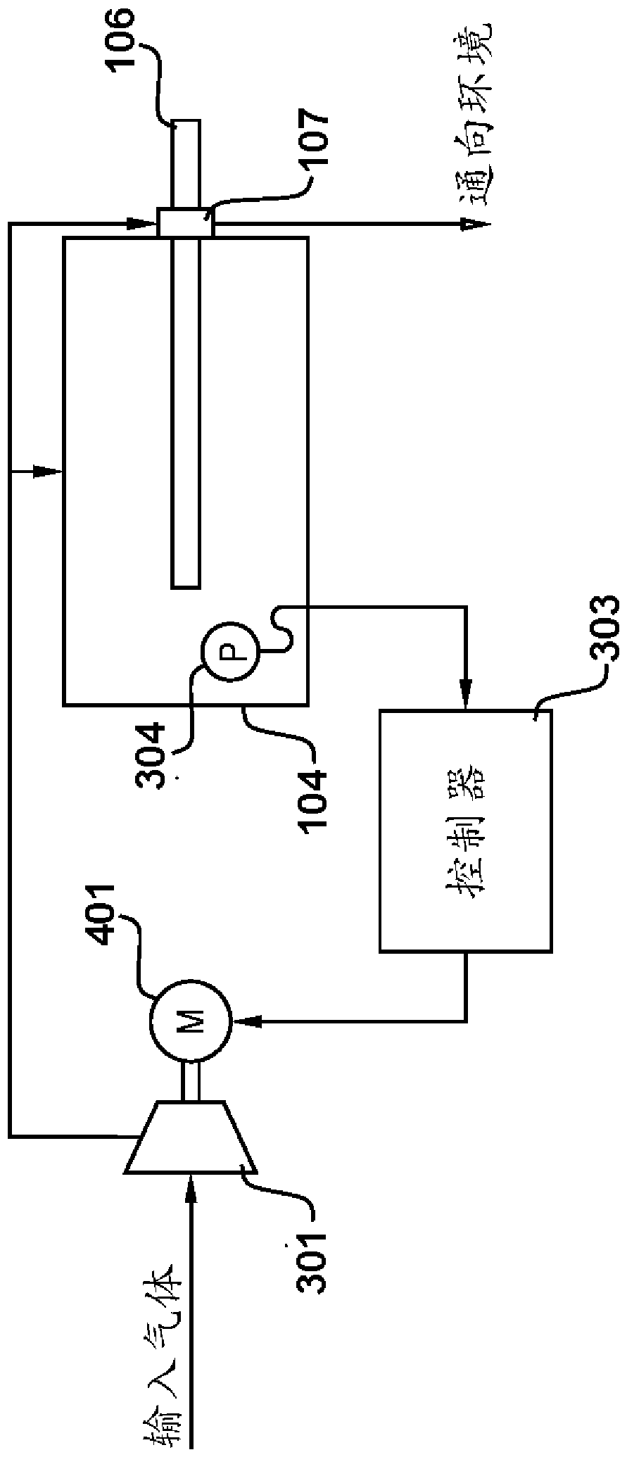
[0020] exist figure 1 A block diagram illustrating an embodiment is shown in , where the motor is shown generally at 101 . The electric machine 101 includes a booster system 102 that receives a supply of input gas from an input gas source 103 . The input gas source 103 may be atmospheric air or, as previously mentioned, a source of pre-pressurized gas, such as an aircraft's bleed air system or cabin exhaust.

[0021] The pressurization system 102 operates to pressurize the housing 104 of the electric machine 101 above the external pressure of the environment 105 in which the electric machine 101 is located.

[0022] The housing 104 houses electromechanical components (not shown) that effectuate the conversion of electrical power into work on the shaft 106 or vice versa depending on the assigned role of the electric machine 101 (eg whether operating as a motor or a generator). It will be appreciated that the exact configuration of the electromechanical components within the h...


PUM


Abstract

An electric machine (101) for an aircraft is shown. The electric machine has a casing (104) containing electrical and electromechanical components, a shaft (106) which extends outside of the casing and which is connected to the propulsive fan, a seal (107) to seal the casing around the shaft, and a pressurization system (102) which pressurises the casing above an external pressure to prevent electrical breakdown within gas in the casing of the electric machine.

Description

technical field [0001] The invention relates to the prevention of arcing in electrical machines in gaseous environments where electrical breakdown may occur. Background technique [0002] At sea level, the dielectric strength of air is typically in the megavolt range. However, in regions of low pressure, such as experienced by aircraft at cruising altitudes, the dielectric strength may drop to the order of only a few hundred volts. [0003] Electric motors (a term understood to include electric motors, generators and other electromagnetic machines and combinations thereof) are typically subjected to voltage derating as altitude increases to prevent electrical breakdown and attendant phenomena that can lead to catastrophic failure modes ( such as arcing and corona). [0004] Current thinking suggests that electric motors will play an increasingly important role in efforts to reduce aircraft fuel consumption, perhaps by being embedded in a hybrid gas turbine engine or by for...

Claims


Application Information

Patent Timeline
IPC IPC(8): H02K5/04H02K5/124
CPCH02K5/04H02K5/124H02K5/12H02K2205/09B64D27/24Y02T50/60F02C3/04B64D27/026B64D13/02B64D27/10F01D15/08B64D13/06
Inventor A.M.Y.拉扎克E.F.H.庄
Owner ROLLS ROYCE PLC
Why Eureka
Eureka Blog
Learn More