
Imaging system and method for realizing large-field wide area searching by utilizing small-field camera

An imaging system and imaging method technology, which is applied in the field of imaging systems for wide-area search with a large field of view, can solve the problems of high-resolution imaging requirements that cannot be met at the same time, and that the field of view is discontinuous, and achieve improved detection capabilities, simple production, and simple structure Effect

Active Publication Date: 2018-12-07
CHANGCHUN INST OF OPTICS FINE MECHANICS & PHYSICS CHINESE ACAD OF SCI
View PDF8 Cites 6 Cited by
  • Summary
  • Abstract
  • Description
  • Claims
  • Application Information

AI Technical Summary

Problems solved by technology

[0004] In order to solve the problem that the structure of the existing imaging system is light and simple and the demand for high-resolution imaging of a large field of view cannot be satisfied at the same time, and the problem that the field of view obtained by the imaging method is discontinuous, the present invention provides a wide-area search for a large field of view by using a small field of view camera The imaging system and method break through the bottleneck of the conventional camera using the traditional imaging mode for imaging with a small field of view, and realize the use of a remote sensing platform equipped with a small field of view imaging load to image a large field of view and a wide area

Method used


Image

  • Imaging system and method for realizing large-field wide area searching by utilizing small-field camera
  • Imaging system and method for realizing large-field wide area searching by utilizing small-field camera
  • Imaging system and method for realizing large-field wide area searching by utilizing small-field camera

Examples


Embodiment Construction

[0025] In order to understand the above-mentioned purpose, features and advantages of the present invention more clearly, the present invention will be further described in detail below in conjunction with the accompanying drawings and specific embodiments.

[0026] In the following description, many specific details are set forth in order to fully understand the present invention. However, the present invention can also be implemented in other ways different from those described here. Therefore, the protection scope of the present invention is not limited by the specific details disclosed below. EXAMPLE LIMITATIONS.

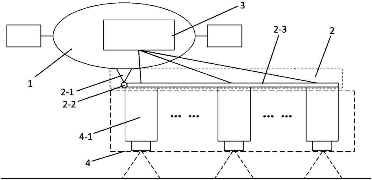
[0027] An imaging system that uses a small field of view camera to realize a wide field search of a large field of view, such as figure 1 It includes a remote sensing platform 1 , a rotating mechanism 2 , an imaging load group 4 and an imaging solution module 3 . The rotating mechanism 2 is connected to the remote sensing platform 1, and the rotating mechanism ...


PUM


Abstract

The invention discloses an imaging system and method for realizing large-field wide area searching by utilizing a small-field camera, and relates to the technical field of the remote sensing camera imaging. The problems that the light structure and the large-field high-resolution imaging demand of the imaging system cannot be simultaneously satisfied, and the fields obtained through the imaging method are discontinuous are solved. The system comprises a remote sensing platform, a rotating mechanism for connecting the remote sensing platform and rotating around the remote sensing platform, multiple imaging load system arranged on the rotating mechanism along the length direction thereof, and an imaging resolution module connected with the remote sensing platform and each imaging load system; the imaging resolution module controls the attitude adjusting of the remote sensing platform, controls the maneuvering adjustment and imaging of the imaging load systems, and controls the rotation of the rotating mechanism through the remote sensing platform. The method comprises the following steps: respectively computing the imaging frame interval of the imaging load system and the required amount of the imaging load system, and selecting the imaging load system and shooting. The imaging system disclosed by the invention satisfies the light structure and large-field high-resolution imagingdemand, and the large-field wide area searching is realized by using the small field camera.

Description

technical field [0001] The invention relates to the technical field of imaging mode design and application of a remote sensing camera, in particular to an imaging system and method for realizing a wide-area search of a large field of view by using a camera with a small field of view. Background technique [0002] The quality, volume, resolution, and width of the imaging system of aerospace remote sensing cameras have always been mutually restricted. In the traditional design ideas of aerospace remote sensing cameras, in order to achieve high-resolution and wide-format imaging, the entire imaging system must The caliber, focal length and other indicators will inevitably increase significantly, which directly brings about the improvement of the quality and volume of the imaging system itself, which in turn leads to an increase in the volume of the remote sensing platform. In applications such as wide-area search, remote sensors are required to have a large field of view, and t...

Claims


Application Information

Patent Timeline
Patent Type & Authority Applications(China)
IPC IPC(8): H04N5/232H04N5/247G05D3/12H04N23/90
CPCG05D3/12H04N23/698H04N23/90
Inventor 曲宏松宋明珠金光张贵祥郑亮亮陶淑苹
Owner CHANGCHUN INST OF OPTICS FINE MECHANICS & PHYSICS CHINESE ACAD OF SCI
Learn More