
A vacuum coating chamber of an automatic vacuum coating production line

An automatic production line and vacuum coating technology, which is applied in the field of machinery, can solve the problems of low automation, high energy consumption, and low efficiency, and achieve the effect of improving production efficiency and uniform coating

Active Publication Date: 2021-04-20
YIBIN PLASTIC PACKAGING MATERIALS CO LTD SICHUAN
View PDF3 Cites 0 Cited by
  • Summary
  • Abstract
  • Description
  • Claims
  • Application Information

AI Technical Summary

Problems solved by technology

The existing coating line goes through: upper part - surface treatment - primer spray - hot air + UV curing - manual transfer to the coating piece to the keel - manual transfer of a single keel to the coating machine - coating - manual Moving off the coated keel—manually transferring the coated parts to the main transmission line—spraying oil—hot air + UV curing—the next piece—quality inspection and other process routes, using a single coated piece as the carrier, there is a labor demand Disadvantages such as large size, high labor intensity of employees, low degree of automation, high three wastes, and low efficiency
The relevant mechanisms of the production line are not fully automatic or have a low degree of automation. As a result, in the production process, it generally takes 20 to 30 people to complete a coating, which leads to high production costs, and the handling process is mainly manual, which increases the instability of the production process. At the same time, the solvent-based ink used for the production of ink smells, the air emission of drying is polluted and cannot be reused, and the energy consumption is high and the environment is polluted.

Method used


Image

  • A vacuum coating chamber of an automatic vacuum coating production line
  • A vacuum coating chamber of an automatic vacuum coating production line
  • A vacuum coating chamber of an automatic vacuum coating production line

Examples


Embodiment Construction

[0029] The present invention will be further described below in combination with specific embodiments and accompanying drawings.

[0030] In order to make the object, technical solution and advantages of the present invention clearer, the present invention will be further described in detail below in conjunction with the accompanying drawings and embodiments. It should be understood that the specific embodiments described here are only used to explain the present invention, and are not intended to limit the present invention

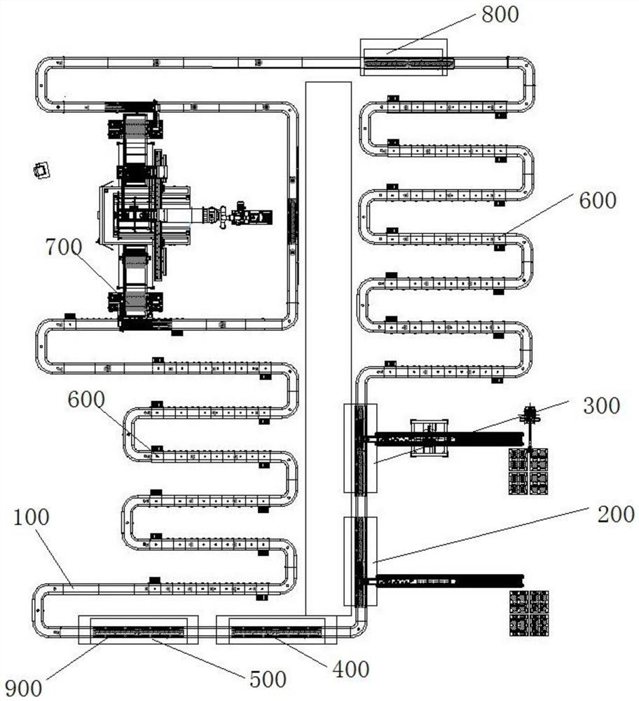
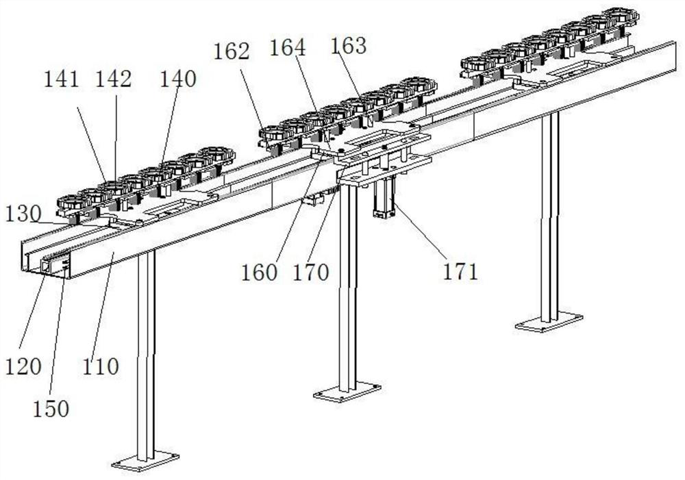
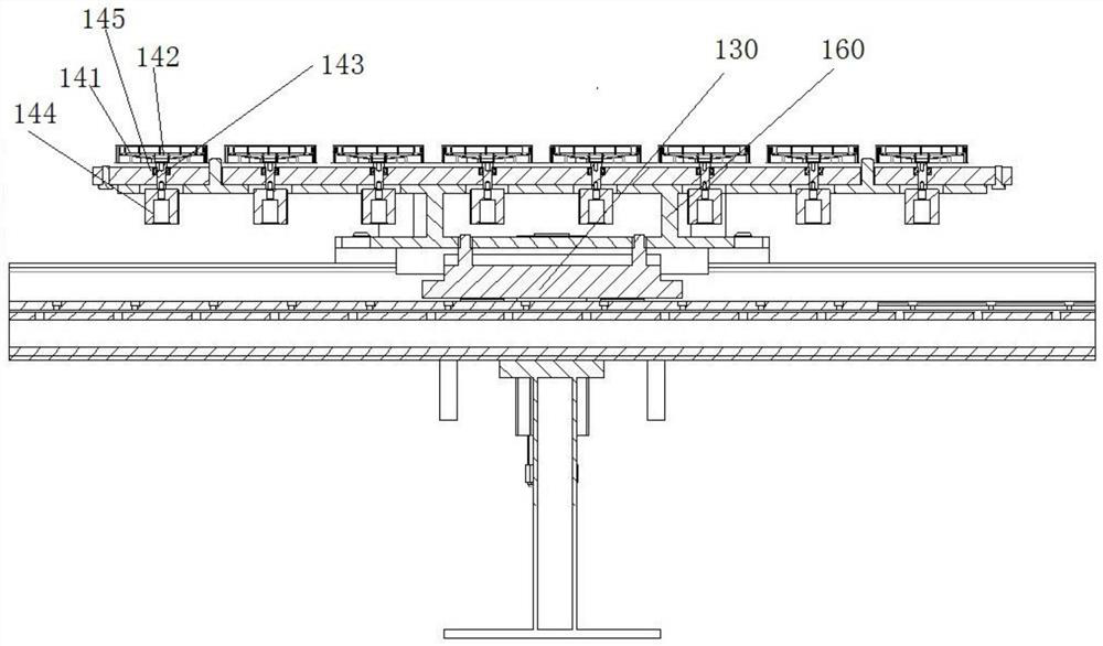
[0031] Such as Figure 1-15For an embodiment of the present invention applied to a vacuum coating automatic production line, a vacuum coating automatic production line includes: a transport structure 100 connected end to end, the transport structure 100 has a feeding structure 200, and the feeding structure 200 The end along the transportation direction of the transportation structure 100 is provided with an unloading structure 300, and the transportati...


PUM


Abstract

The invention discloses a vacuum coating chamber of a vacuum coating automatic production line, comprising: a main body of the coating chamber, an opening is provided on the top of the main body of the coating chamber, a planar movable top cover is arranged at the opening, and an air chamber is provided on the main side of the coating chamber. Import and export, the air inlet and outlet are connected with the vacuum pump assembly, and a planar movable top cover can be set to realize mechanized loading and unloading. After several keels can be integrated and clamped horizontally, they can be transported and processed as a whole through a mechanized structure. During the working process, the gantry can be rotated in time to make the coating uniform, thereby improving production efficiency and not affecting the normal operation of the production line.

Description

technical field [0001] The invention relates to the mechanical field, in particular to a vacuum coating chamber of an automatic vacuum coating production line. Background technique [0002] Vacuum coating technology first appeared in the 1930s, industrial applications began to appear in the 1940s and 1950s, and industrial mass production began in the 1980s. It has been widely used in electronics, aerospace, packaging, decoration, hot stamping and printing industries. Vacuum coating refers to the deposition of a certain metal or metal compound on the surface of a material (usually a non-metallic material) in the form of vapor in a vacuum environment, which belongs to the physical vapor deposition process. Because the coating is often a metal film, it is also called vacuum metallization. Among all the materials to be plated, plastics are the most common. Plastics have the advantages of sufficient sources, easy control of properties, and convenient processing. Therefore, a wid...

Claims


Application Information

Patent Timeline
Patent Type & Authority Patents(China)
IPC IPC(8): C23C14/56
CPCC23C14/56
Inventor 徐刚王勇熊建周立权高灵强阳培翔
Owner YIBIN PLASTIC PACKAGING MATERIALS CO LTD SICHUAN
Learn More