Oil-saving triangular rotor engine

A triangular rotor and engine technology, which is applied to combustion engines, machines/engines, internal combustion piston engines, etc., can solve the problems of unfavorable mixed gas ignition and flame propagation in multiple directions, unfavorable normal use of triangular rotor engines, incomplete combustion of mixed gas and fuel consumption, etc. , to achieve the effects of accelerating multi-point propagation, simple structure, and shortening the combustion path

Inactive Publication Date: 2018-12-11
NINGBO UNIV
View PDF3 Cites 3 Cited by
  • Summary
  • Abstract
  • Description
  • Claims
  • Application Information

AI Technical Summary

Problems solved by technology

[0003] One of the main problems of triangular rotor engines at present is high fuel consumption. The main reason is that the shape of the combustion chamber is flat and the combustion path is long. This kind of flat combustion chamber is affected by the structure and compression ratio, so it is not easy to improve the structure, and the horizontal airflow of the flat combustion chamber is extremely large, which is not conducive to the ignition of the mixture and the multi-directional propagation of the combustion flame, resulting in The flame propagation is hindered, the mixed gas cannot be completely combusted, and the fuel consumption increases, which is not conducive to the normal use of the triangular rotor engine

Method used


Image

  • Oil-saving triangular rotor engine
  • Oil-saving triangular rotor engine
  • Oil-saving triangular rotor engine

Examples


Embodiment Construction

[0012] The present invention will be further described in detail below in conjunction with the accompanying drawings and embodiments.

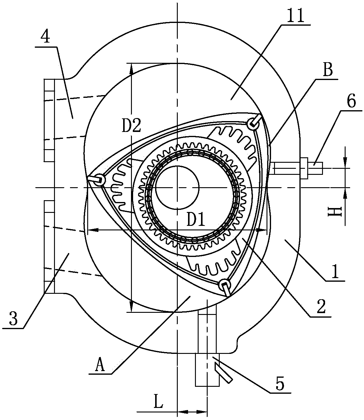
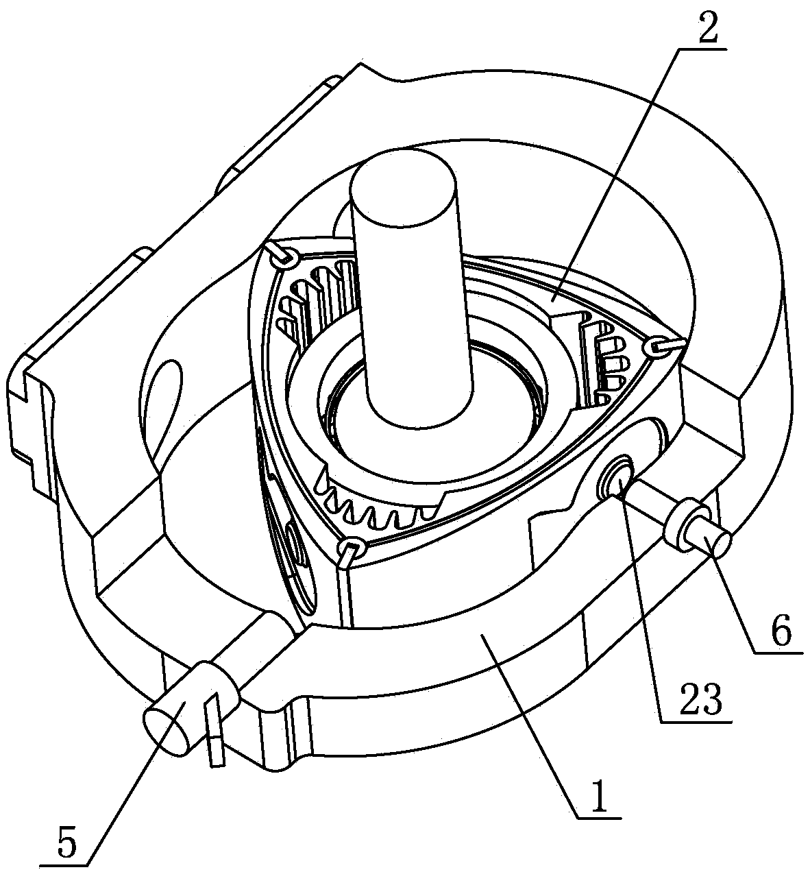
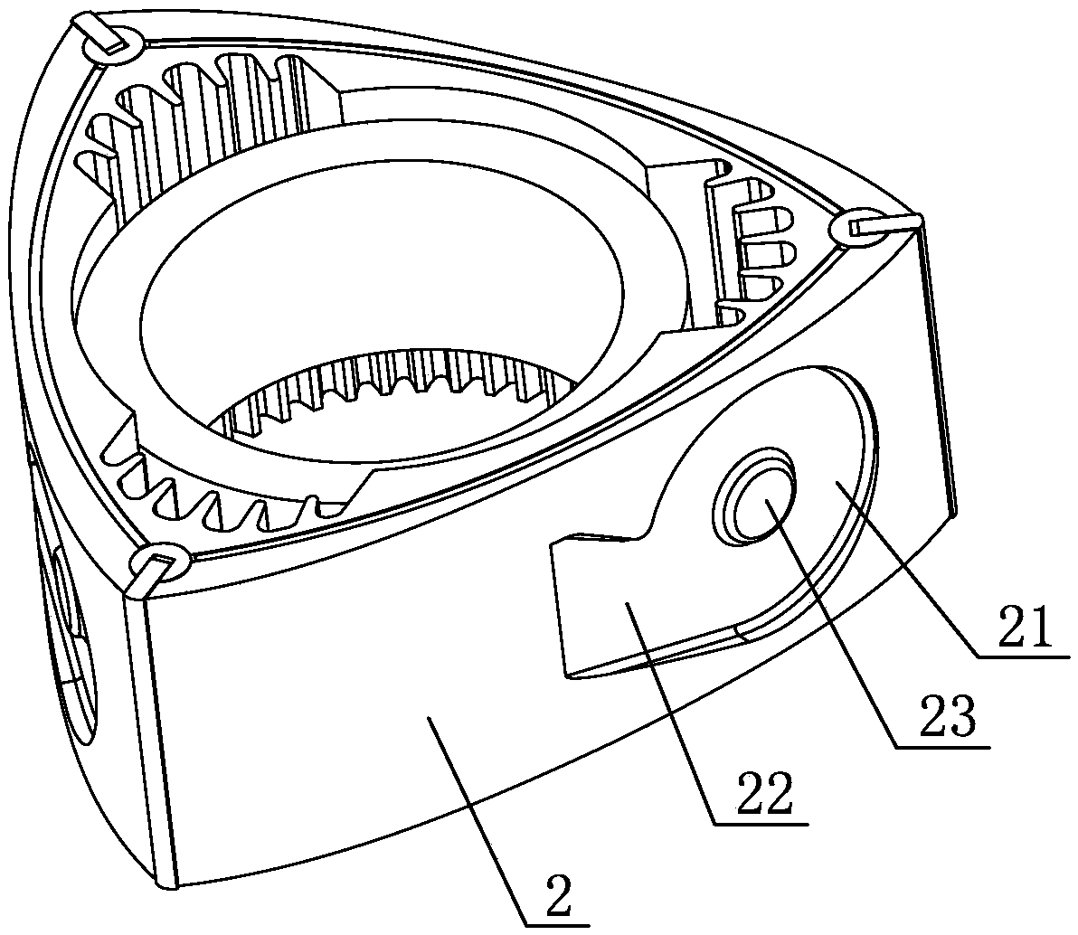
[0013] As shown in the figure, a fuel-saving triangular rotor engine includes a cylinder block 1 and a triangular rotor 2. The cylinder block 1 is provided with an 8-shaped inner cavity 11, the triangular rotor 2 is arranged in the inner cavity 11, and the triangular rotor 2 The three endpoints of the cylinder are in sealing and sliding fit with the inner cavity 11. The cylinder block 1 is provided with an air inlet 3 and an exhaust port 4. The cylinder block 1 is fixedly provided with a fuel injector 5 and an ignition plug 6. The center of the fuel injector 5 The line is parallel to the long axis of the cylinder block 1, and the fuel injection port of the fuel injector 5 is located at the front area A of the air intake chamber in the cylinder block 1, and the centerline of the fuel injector 5 to the long axis of the cylinder block 1 The dista...


PUM


Abstract

The invention discloses an oil-saving triangular rotor engine, which comprises a cylinder body and a triangular rotor. An oil nozzle and an ignition plug are fixedly arranged on the cylinder body. Theoil-saving triangular rotor engine is characterized in that the center line of the oil nozzle is parallel to the long axis of the cylinder body, an oil spraying port of the oil nozzle is positioned in a front area of an air inlet chamber in the cylinder body, the center line of the ignition plug is parallel to the short axis of the cylinder body, and the ignition plug is positioned in a front area of a combustion chamber in the cylinder body; outer side walls of the triangular rotor are provided with circular air guide grooves and air leading grooves, the air leading grooves and the circularair guide grooves are tangential, and the center of each circular air guide groove is provided with a cylindrical boss. The oil-saving triangular rotor engine has advantages that in operation of the engine, an airflow vortex is generated on the outer lateral side of the triangular rotor, mixed gas can be easily ignited by the ignition plug, multi-point spreading of flame is accelerated by the airflow vortex, a burning route is shortened, and burning spreading speed is increased; since the mixed gas is mainly gathered in the front of the combustion chamber, complete combustion of the mixed gasis promoted, and oil consumption is reduced.

Description

technical field [0001] The invention relates to an engine, in particular to an oil-saving triangular rotor engine. Background technique [0002] Triangular rotor engine, also known as Wankel engine, is a four-stroke engine, which is characterized in that the movement of the triangular rotor is planetary rotation through gear meshing. The three vertices of the triangular rotor are close to the inner wall of the cylinder, and the inner cavity of the cylinder is divided into three working areas by the rotor, and the inner cavity of the cylinder is in the shape of an 8. With the rotation of the triangular rotor, four working cycles are performed. [0003] One of the main problems of triangular rotor engines at present is high fuel consumption. The main reason is that the shape of the combustion chamber is flat and the combustion path is long. This kind of flat combustion chamber is affected by the structure and compression ratio, so it is not easy to improve the structure, and ...

Claims


Application Information

Patent Timeline
Patent Type & Authority Applications(China)
IPC IPC(8): F02B55/14F02B53/12F02B53/08
CPCF02B53/08F02B53/12F02B55/14Y02T10/12
Inventor 汤廷孝
Owner NINGBO UNIV
Why Eureka
Try Eureka