Manufacturing method of fin tube typed heat exchanger and combustion apparatus having the same

A heat exchanger and fin-and-tube technology, which is applied in the field of combustion devices, can solve the problems of increased cost, poor productivity of heat exchangers, and condensation of stainless steel, and achieves improved adhesion, higher brazing rate, and higher productivity. Effect

Inactive Publication Date: 2018-12-11
RINNAI CORP
View PDF11 Cites 0 Cited by
  • Summary
  • Abstract
  • Description
  • Claims
  • Application Information

AI Technical Summary

Problems solved by technology

[0004] However, in the case of the heat transfer tube 31 (metal tube) made of stainless steel, when the main body 40 of the tube expansion jig 4 is forcibly inserted and pressed into the heat transfer tube 31, even if lubricating oil is added, the diamond-like carbon film will not The treatment will also peel off early, which will generate more frictional heat and cause the stainless steel to condense on the surface of the main body 40
If the tube expanding jig 4 is continuously used in this state, not only the failure of damage to the inside of the heat transfer tube 31 will be caused, but also the load on the press-fitting of the main body part 40 will increase, and the shaft part 41 may be damaged.
Therefore, the replacement frequency of the tube expansion jig 4 is high, and since the lubricating oil in the heat transfer tube 31 needs to be dried and removed, the productivity of the heat exchanger is very poor, and the cost increase cannot be said to be suitable for mass production. institutional approach

Method used


Image

  • Manufacturing method of fin tube typed heat exchanger and combustion apparatus having the same
  • Manufacturing method of fin tube typed heat exchanger and combustion apparatus having the same
  • Manufacturing method of fin tube typed heat exchanger and combustion apparatus having the same

Examples


Embodiment Construction

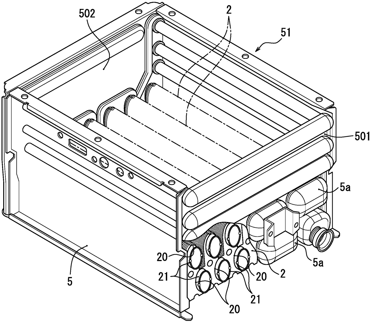
[0051] Below, refer to the attached Figure 1 The mode for carrying out the present invention will be described. figure 1In the shown heat exchanger 51 , between the facing front and rear side walls 501 , 502 of the housing 5 , a plurality of sheet-like heat transfer fins for heat absorption are arranged parallel to the side walls 501 , 502 . slice 2. In addition, in this specification, let the outer surface of the front side wall 501 be the front of the heat exchanger 51, let the depth direction when viewing the casing 5 from the front side be the front-rear direction, let the width direction be the left-right direction, and let the height direction be the front and rear directions. up and down direction.

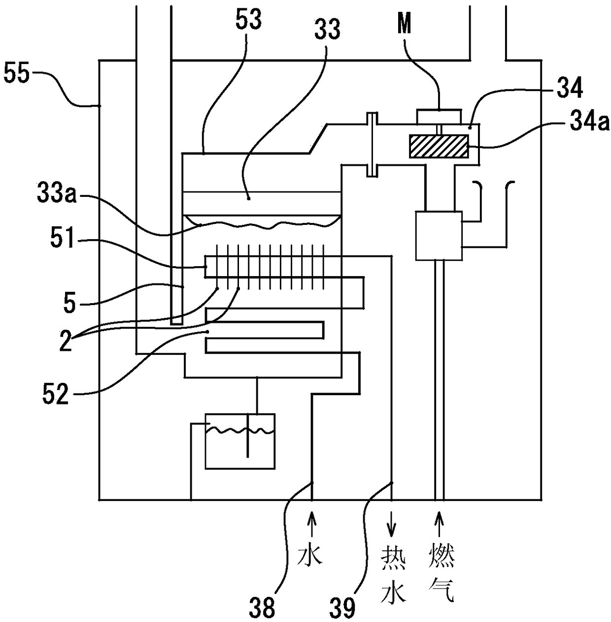
[0052] Heat exchanger 51 is for example in such as figure 2 Shown is for use on water heaters equivalent to combustion units. In this water heater, a casing 55 is provided with: a body 53 having a burner 33 with a downwardly facing combustion surface 33a in an upper ...


PUM


Abstract

Provided are a method for manufacturing a fin tube type heat exchanger that may use a pipe expansion apparatus for a long time and improve productivity, and a combustion apparatus including the fin tube type heat exchanger. The method for manufacturing a fin tube type heat exchanger (51) includes: a pipe expanding process of expanding a thermoelectric pipe (21) by inserting a pipe expansion apparatus (100) into the thermoelectric pipe (21) inserted into an insertion hole (20) of a thermoelectric fin (2). The pipe expanding process includes: a first process of expanding a thermoelectric pipe (21) such that an enlarged diameter prediction range (22) to an insertion hole (20) by expanding the thermoelectric pipe (21) radially into a diameter expansion state in a state in which a pipe expansion apparatus (100) is stopped in the enlarged diameter prediction range (2) in the thermoelectric pipe (21); and a second process of moving the pipe expansion apparatus (100) to the next enlarged diameter prediction range (22) in the thermoelectric pipe (21) in an enlarged diameter state by releasing the expansion of the pipe expansion apparatus (100) in a radial direction. The first process and the second process are performed repeatedly and alternately.

Description

technical field [0001] The present invention relates to a method of manufacturing a fin-tube heat exchanger and a combustion device provided with the fin-tube heat exchanger. Background technique [0002] As a heat exchanger assembled on a water heater, such as Figure 7 As shown, there is a fin-and-tube heat exchanger in which a plurality of thin-plate-shaped heat transfer fins 3 are arranged side by side with predetermined gaps therebetween, and heat transfer tubes 31 are inserted into the pipe holes provided on the respective heat transfer fins 3 . jack 30 in. In order to improve the thermal efficiency, it is desirable that the peripheral edge of the tube insertion hole 30 of the heat transfer fin 3 is in close contact with the outer peripheral surface of the heat transfer tube 31 and the heat transfer tube 31 is expanded so that there is no gap between them. [0003] For example, Japanese Patent Application Laid-Open No. 2008-93713 discloses a method for expanding a met...

Claims


Application Information

Patent Timeline
Patent Type & Authority Applications(China)
IPC IPC(8): F24H9/00F24H9/18
CPCF24H9/0005F24H9/1836B21D39/20B21D53/06F24H1/40F24H9/0026F28D1/0426F28D1/0477F28D2021/0024F28F1/30F28F1/32F28F2255/00F28F1/02F28F1/325F28F2215/08
Inventor 伊藤尚宏武藤诚一
Owner RINNAI CORP
Why Eureka
Try Eureka