Hydrofoil surface fluid resistance testing device capable of achieving flow jetting

A testing device and fluid resistance technology, which is applied in the direction of fluid dynamics test, measuring device, machine/structural component testing, etc. It can solve problems such as difficult installation and disassembly, difficult jet surface resistance measurement, cumbersome operation, etc., to achieve convenient loading and unloading , low cost and wide application range

Pending Publication Date: 2018-12-11
ZHEJIANG UNIV OF TECH
View PDF5 Cites 6 Cited by
  • Summary
  • Abstract
  • Description
  • Claims
  • Application Information

AI Technical Summary

Problems solved by technology

[0003] Aiming at the problems that the existing fluid resistance test device occupies a large area, high cost, cumbersome operation, not easy to install and disassemble, and difficult to measure the resistance of the jet surface, the present invention proposes a hydrofoil surface fluid resistance test that can realize the jet flow The purpose of the device is to evaluate the drag reduction effect of other different structures on the basis of realizing the evaluation of the drag reduction effect of the jet surface structure

Method used


Image

  • Hydrofoil surface fluid resistance testing device capable of achieving flow jetting
  • Hydrofoil surface fluid resistance testing device capable of achieving flow jetting
  • Hydrofoil surface fluid resistance testing device capable of achieving flow jetting

Examples


Embodiment 1

[0029] Embodiment 1 A kind of hydrofoil surface fluid resistance testing device that can realize jet flow according to the present invention includes:

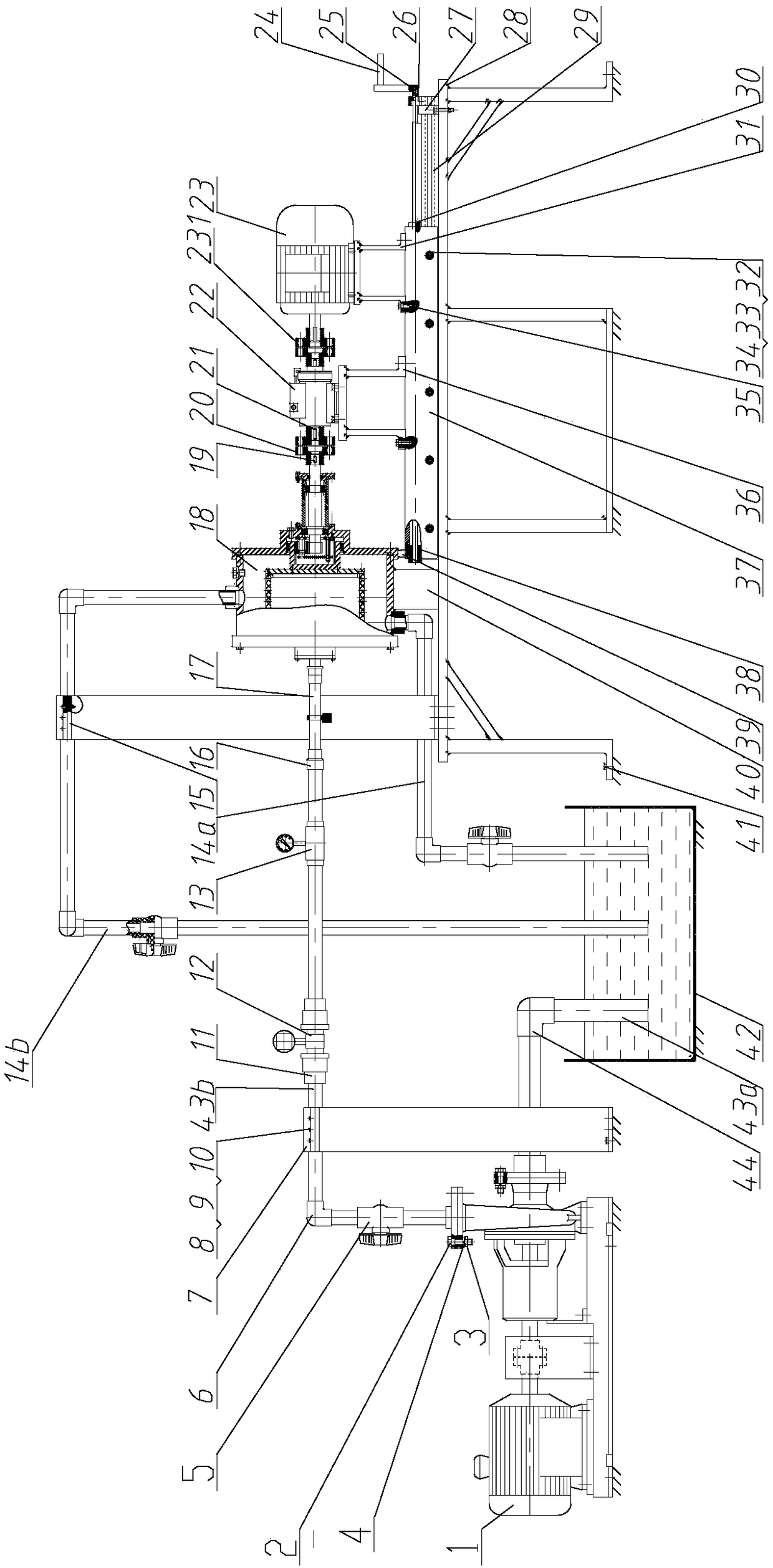
[0030] The frame body includes a test platform support 28 with a working platform and a position adjustment device installed on the working platform, wherein the fixing part of the position adjusting device is paved on the working platform, and the fixing part can be installed along the axial direction of the fixing part. Sliding moving parts, used to adjust the power transmission system and the installation position of the hydrofoil test sample test system;

[0031] The power transmission system includes a drive device, a torque signal acquisition unit and a force transmission unit. The drive device and the torque signal acquisition unit are coaxially installed on the moving part of the position adjustment device, and the power output end of the drive device is connected to the power of the torque signal acquisition unit. The...

Embodiment 2

[0046] Embodiment 2 A hydrofoil surface fluid resistance testing device capable of jet flow according to the present invention includes a frame body, a power transmission device, a hydrofoil test sample testing device and a water supply device, and the power transmission device is installed on the on the frame, and the power output end of the power transmission device is connected to the hydrofoil test sample testing device, and the water supply device is used to provide the water flow velocity for the device test, and is arranged on the hydrofoil The side of the test sample testing device away from the power transmission end is connected with the frame body.

[0047] combine figure 1 , figure 2 , in the input gear shaft of the power transmission device: the motor support 31 is installed on the rail platform 37 of the frame body, the motor 23 is installed on the motor support 31, the The output shaft of the motor 23 is affixed to the power input end of the torque signal cou...


PUM


Abstract

The invention discloses a hydrofoil surface fluid resistance testing device capable of achieving flow jetting, and the device comprises a frame body which comprises a test platform support seat with aworking platform, and a position adjustment device installed on the working platform; a power transmission system which comprises a drive unit, a torque signal collection unit and a force transmission unit, wherein the drive unit and the torque signal collection unit are coaxially installed on a moving part of the position adjustment device; a hydrofoil test sample testing system which comprisesa sealing cylinder assembly for sealing, a test cylinder assembly for installing a hydrofoil test sample, and a water leading unit which is used for leading water to the inner cavity of the test cylinder assembly; and a water supply system which comprises a water pump, a first water incoming pipe, a second water incoming pipe, a first water outgoing pipe, a second water outgoing pipe, and a watertank. The beneficial effects of the invention are that the device is small in size, is compact and simple in structure, is low in cost, is simple in operation, is high in test performances, is not limited by the surrounding test environment, and facilitates the loading and unloading of the hydrofoil test sample.

Description

technical field [0001] The invention relates to a hydrofoil surface fluid resistance testing device capable of realizing jet flow. Background technique [0002] In recent years, bionics has been one of the hot issues of domestic and foreign researchers. For example, the bionic jet surface drag reduction technology derived from the gill slit jet function in the shark breathing process has obvious drag reduction effect and is an effective active control method, and its jet action can optimize the wall fluid The boundary layer structure then achieves the purpose of reducing the fluid frictional resistance of the solid wall. If this drag reduction technology can be applied to the drag reduction of the hull surface of underwater vehicles, it will play an important role in increasing the speed of the ship and saving energy. certain military role. There has been relatively little research on bionic jet surface drag reduction technology. The current research on jet mainly focuses ...

Claims


Application Information

Patent Timeline
Patent Type & Authority Applications(China)
IPC IPC(8): G01M10/00
CPCG01M10/00
Inventor 谷云庆夏轲余松伟牟介刚吴登昊郑水华周佩剑章子成
Owner ZHEJIANG UNIV OF TECH
Why Eureka
Try Eureka