

Method for measuring large-stress range stress strain in uniaxial tensile test of metal round bar sample
A technology of uniaxial tension and measurement method, which is applied in the direction of applying stable tension/pressure to test the strength of materials, etc., which can solve the problems of large error and cumbersome measurement, and achieve the goal of saving measurement time, having operability and saving measurement cost Effect
- Summary
- Abstract
- Description
- Claims
- Application Information
AI Technical Summary
Problems solved by technology
Method used
Image

Examples
Embodiment 1
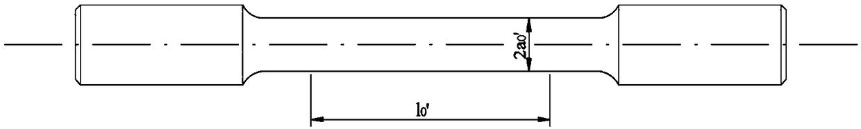
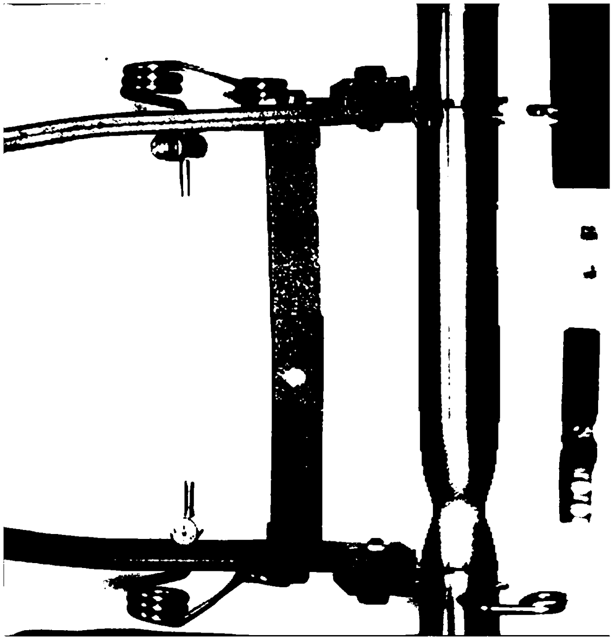
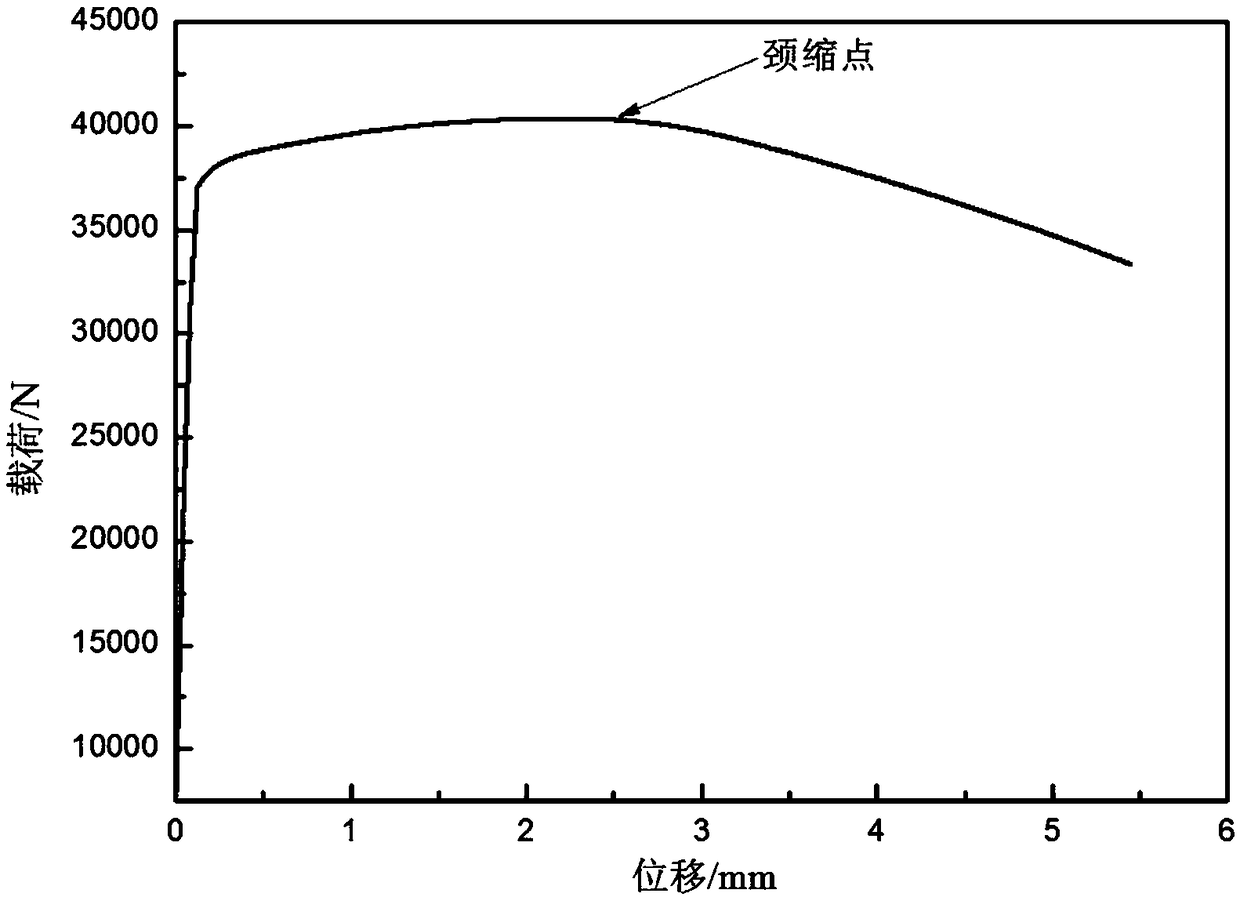
[0035] (1) The present invention takes the low carbon steel round bar sample as an example, adopts figure 1 The shown round bar sample is subjected to uniaxial tensile test, the initial cross-sectional diameter of the round bar sample is 10 mm, and the gauge length section is 50 mm. Such as figure 2 As shown, the extensometer is used to measure and record the load F at each moment from the point of maximum load (neck point) to before fracture i and the instantaneous gauge length l i , formed as image 3 For the load-displacement curve shown, use the optical measurement method to record the minimum section radius a of the necking at each moment i . Where i=0~N, 0 and N correspond to the maximum load point (neck point) and the break point moment respectively;
[0036] (2) After the necking instability, the metal round bar sample always diffuses and deforms at the minimum necking point, and does not participate in the deformation outside the minimum necking point. Such as ...
Embodiment 2
[0051] The finite element analysis software ABAQUS is used to simulate the uniaxial tensile process of the round bar sample. According to the size and conditions of the uniaxial round bar sample in Example 1, the finite element model of the uniaxial tensile test process is established, and the input preset The stress-strain curve of the sample is used as a material model, and the same constraints and loading conditions are used in the simulation analysis and the test of Example 1. One end is fixed in the axial direction, and the other end is loaded with the same speed load as the axial direction of the sample, and the tensile process of the test sample is simulated. According to the method of obtaining data in the tensile test, the difference between the displacements of the two sections of the gauge length section of the simulation result is taken as the displacement value, and the resultant force of the interface of the gauge length section obtained by simulation is used to dr...
PUM
 Abstract
Description
Claims
Application Information