
Novel high-sensitivity photonic-crystal optical fiber sensor

A photonic crystal fiber, high-sensitivity technology, applied in the direction of converting sensor output, using optical devices to transmit sensing components, cladding optical fibers, etc., can solve the problems of difficult filling of the liquid to be tested, difficulty of coating small-sized air holes, etc.

Inactive Publication Date: 2018-12-11
NORTH CHINA UNIV OF WATER RESOURCES & ELECTRIC POWER
View PDF9 Cites 4 Cited by
  • Summary
  • Abstract
  • Description
  • Claims
  • Application Information

AI Technical Summary

Problems solved by technology

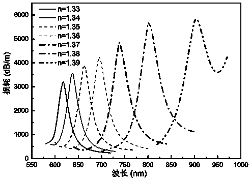
The optical fiber is a newly designed three-bridge photonic crystal fiber with a Leroux triangular structure. After polishing a large air hole, an open groove is formed. The groove is coated with a gold nano-film near the core, and the liquid to be tested is placed in the groove. The inside does not need to be connected to a closed air hole, which solves the problems of difficult coating of small-sized air holes and difficult filling of the liquid to be tested

Method used


Image

  • Novel high-sensitivity photonic-crystal optical fiber sensor
  • Novel high-sensitivity photonic-crystal optical fiber sensor
  • Novel high-sensitivity photonic-crystal optical fiber sensor

Examples


Embodiment Construction

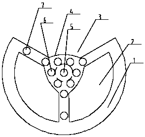
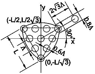
[0025] Such as figure 1 and figure 2 A kind of novel high-sensitivity photonic crystal fiber sensor shown, comprises base material 1, is provided with photonic crystal fiber cladding and fiber core on base material, base material is silicon dioxide, is circular in shape and on circular base The material is provided with an open groove 3, and the open groove is composed of a large air hole that has been polished in the photonic crystal fiber. The cladding is composed of two large air holes 2 and small air holes 6, 7. The cross-sections of the two large air holes are fan-shaped, and the curves of the fan surfaces on both sides of the two large air holes are part of the Relau triangle and the circle respectively. , the arcs of the inner fans of the two large air holes and the arcs of the bottom arc of the groove are the three arcs of the Leroux triangle respectively, the distance between the adjacent large air holes, and the distance between the large air hole and the groove ar...


PUM

PropertyMeasurementUnit
Arc radiusaaaaaaaaaa
Radiusaaaaaaaaaa
Thicknessaaaaaaaaaa

Abstract

The invention relates to a novel high-sensitivity photonic-crystal optical fiber sensor. The novel high-sensitivity photonic-crystal optical fiber sensor comprises a substrate material, wherein a photonic crystal optical fiber cladding and a fiber core are arranged on the substrate material, the substrate material is circular, an open groove is formed in the circular substrate material, a camberedshape of the open groove is one cambered surface of a Reuleaux triangle, the photonic crystal optical fiber cladding consists of two big air holes and small air holes, cross sections of the two big air holes are fan-shaped, curved lines, where sectors of two sides of the two big air holes are located, are one part of the Reuleaux triangle and one part of a circle separately, arc lines, where inner sectors of the two big air holes are located, and an arc, where an cambered surface of the bottom of the groove is located, are three arcs of the Reuleaux triangle separately, bridge arms are arranged between the big air holes and the groove among the big air holes and are connected with the Reuleaux triangle, the small air holes consist of bridge-arm small air holes and cladding small air holes, the bridge-arm small air holes are formed in the bridge arms, the cladding small air holes are formed in the Reuleaux triangle, a low-refractive-index liquid hole is formed in the center position ofthe Reuleaux triangle, and a gold nano-film is arranged on the cambered surface of the bottom of the groove.

Description

technical field [0001] The invention relates to the technical field of photonic crystal fiber sensing, in particular to the technical field of high-sensitivity sensing and detection. Background technique [0002] Surface plasmon resonance (SPR) technology has always attracted the interest of researchers in related fields because of its unique advantages. As one of the applications of SPR technology, SPR-based optical fiber sensing technology has also been explored and improved. Ordinary optical fibers have disadvantages such as becoming brittle and easily damaged after being polished, complex polishing process and difficult phase matching. These shortcomings have been solved after the emergence of photonic crystal fibers. Photonic crystal fiber evanescent wave sensing technology can be divided into photonic crystal fiber evanescent wave absorption sensing technology, photonic crystal fiber evanescent wave excited fluorescent label sensing technology and photonic crystal fibe...

Claims


Application Information

Patent Timeline
IPC IPC(8): G01N21/59G01D5/26G02B6/02
CPCG01D5/268G01N21/59G02B6/02295G02B6/02314
Inventor 邴丕彬黄世超隋佳蕾国馨月李忠洋谭联周玉袁胜王花
Owner NORTH CHINA UNIV OF WATER RESOURCES & ELECTRIC POWER
Learn More