Random evolution constraint SAR radiometric calibration method

A radiation calibration and calibration technology, applied in the direction of radio wave reflection/re-radiation, using re-radiation, measurement devices, etc., can solve the radar cross-section measurement error, difficulty in achieving specified accuracy, abnormality of the sample data set of the calibrator, etc. problem, achieve the effect of reducing impact and enhancing robustness

Active Publication Date: 2018-12-11
CHINA ELECTRONIC TECH GRP CORP NO 38 RES INST
View PDF6 Cites 6 Cited by
  • Summary
  • Abstract
  • Description
  • Claims
  • Application Information

AI Technical Summary

Problems solved by technology

However, the corner reflectors will cause errors in the radar cross-section measurement during the process of manufacturing, processing and layout. These errors include surface irregularities, plate curvature, plate axis alignment, equipment pointing, background backscattering effects, and multipath scattering. etc., thus introducing anomalies in the sample data set of the calibrator, resulting in the deterioration of the radiation calibration accuracy or difficulty in reaching the specified accuracy
At the same time, in the post-calibration process, it is often difficult to distinguish which calibrators are outliers (i.e. outliers), and whether the size of the anomaly affects the required calibration accuracy

Method used


Image

  • Random evolution constraint SAR radiometric calibration method
  • Random evolution constraint SAR radiometric calibration method
  • Random evolution constraint SAR radiometric calibration method

Examples


Embodiment 1

[0064] This embodiment is an X-band airborne SAR image radiation calibration method.

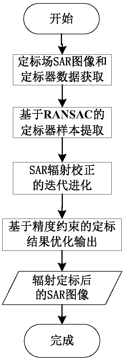
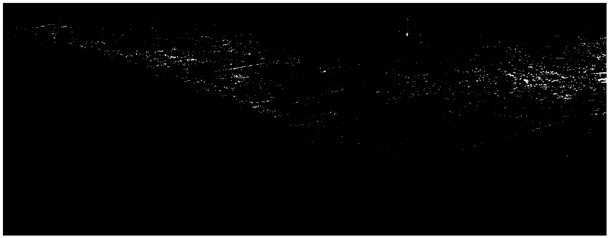
[0065] Such as figure 1 with figure 2 As shown, this embodiment first obtains an X-band airborne SAR image of a domestic SAR flying in a calibration field according to step (1). figure 2 It is the SAR image of the original HH polarization channel of the calibration field, the image size is 3000 pixels * 8192 pixels, the radar wavelength λ is 0.03125m, the flying height H is 3787.46m, and the initial slant distance R 0 It is 4054.97m, the range (Y direction) resolution ΔY is 0.2998m, and the azimuth (X direction) resolution ΔX is 0.3003m. Due to the system transfer function With the existence of, the original SAR image shows obvious changes in brightness, that is, the brightness at the top of the image is brighter, and the brightness at the bottom of the image is darker. 8 (i.e. N all =8) Square trihedral corner reflectors with side length b of 0.45m. See Table 1 for their positions in the im...

Embodiment 2

[0075] This embodiment analyzes the X-band SAR data.

[0076] First, obtain the X-band airborne SAR image of the domestic SAR flying in a certain calibration field according to step (1), Figure 7 It is the SAR image of the original HH polarization channel of the calibration field, the image size is 6021 pixels * 8192 pixels, the radar wavelength λ is 0.03125m, the flying height H is 4000m, and the initial slant distance R 0 It is 4882.66m, the range (Y direction) resolution ΔY is 0.2998m, and the azimuth (X direction) resolution ΔX is 0.3003m. Due to the system transfer function With the existence of, the original SAR image shows obvious changes in brightness, that is, the brightness at the top of the image is brighter, and the brightness at the bottom of the image is darker. 9 (i.e. N all =9) Square trihedral corner reflectors with side length b of 0.30m, and their positions in the image are shown in Table 2.

[0077] In addition, considering the actual application and the accur...


PUM


Abstract

The invention discloses a random evolution constraint SAR radiometric calibration method, and the method comprises the following steps: obtaining a SAR image of a calibration field and the informationof a calibrator, and setting a calibration precision threshold value zeta<thred>; performing the random sampling of a sample interior point of the calibrator; performing the iterative evolution of the SAR radiometric calibration; and performing the optimization and outputting of a calibration result based on the precision constraint. The method obtains the image of the calibration field and the data and information of the calibrator through the imaging flight of an aerial carrier, employs as few sample points as possible for estimation and calibration via the random sampling of the sample interior points of the calibrator, the given constraint meeting of the precision of radiometric calibration and the iterative evolution of the number of sample interior points and the number of curve fitting orders through combining a random sampling consistency model and a conventional SAR radiometric calibration method, achieves the verification of the calibration precision through the adding of the remaining sample points, irons out the defects of the conventional SAR radiometric calibration method, alleviates the impact on the precision of the radiometric calibration from abnormal data when there is a severely wrong point, and greatly improves the robustness of the SAR radiometric calibration.

Description

Technical field [0001] The invention relates to an airborne synthetic aperture radar (SAR) data external radiation calibration processing technology, in particular to a random evolutionary constraint SAR radiation calibration method. Background technique [0002] Synthetic Aperture Radar (SAR) is an active microwave remote sensing imaging radar. Due to its all-weather and all-weather advantages, it is particularly suitable for large-area surface imaging, and it also promotes its application in the investigation of earth resources. At present, synthetic aperture radar images have been widely used in geology, hydrology, agriculture, forestry, cities, oceans, surveying and mapping, and military reconnaissance. [0003] Initially, the application of SAR data was mainly based on the information about the position, shape and relative change of the target echo provided by the image, that is, qualitative remote sensing technology. The application of qualitative remote sensing technology i...

Claims


Application Information

Patent Timeline
Patent Type & Authority Applications(China)
IPC IPC(8): G01S7/40G01S13/90
CPCG01S7/40G01S13/90
Inventor 陈曦钟雪莲许涛吴涛牛蕾
Owner CHINA ELECTRONIC TECH GRP CORP NO 38 RES INST
Why Eureka
Try Eureka