A method for modeling rigidity of a transmission chain of a double-screw drive system

A technology of driving system and modeling method, applied in the field of dynamics, which can solve the problems of finite element method relying on mesh accuracy calculation efficiency, increasing calculation error, ignoring joint surface stiffness and damping, etc.

Active Publication Date: 2018-12-11
WUHAN UNIV OF TECH
View PDF3 Cites 14 Cited by
  • Summary
  • Abstract
  • Description
  • Claims
  • Application Information

AI Technical Summary

Problems solved by technology

[0003] At present, although the empirical formula method, analytical method and finite element method have appeared for the calculation of the stiffness of the single screw transmission chain, these calculation methods have various deficiencies and problems. The empirical formula method has large errors, and the process of the analytical method is very complicated. The finite element method relies heavily on grid accuracy and has low calculation efficiency, and ignores the stiffness and damping of the joint surface for dynamic calculations, which greatly increases the calculation error; while in the field of double-screw drive, due to the coupling characteristics of the double-screw, There are relatively few dynamic models for the double-screw drive system, and there is almost no accurate model for calculating the stiffness of the double-screw drive chain; according to statistics, more than 60% of the vibration problems on the machine tool come from the joint surface, and the joint surface stiffness can be used To characterize the stiffness of the machine tool, more than 90% of the damping comes from the joint surface damping

Method used


Image

  • A method for modeling rigidity of a transmission chain of a double-screw drive system
  • A method for modeling rigidity of a transmission chain of a double-screw drive system
  • A method for modeling rigidity of a transmission chain of a double-screw drive system

Examples


Embodiment Construction

[0066] In order to make the object, technical solution and advantages of the present invention clearer, the present invention will be further described in detail below in conjunction with the accompanying drawings and embodiments.

[0067] This example relies on the self-developed double-screw-driven workbench system, such as figure 2 shown.

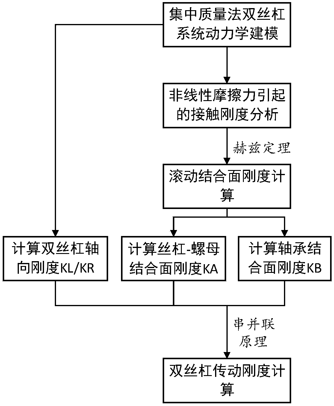
[0068] A modeling method for the stiffness of the transmission chain of a double-screw drive system, such as figure 1 shown, including the following steps:

[0069] Step1, calculate the contact stiffness of the rolling contact surface. The rolling joint surface includes the screw-nut joint surface and the bearing joint surface. It is assumed that the contacting rolling elements between the contact surfaces obey the Hertz contact theory, and the mutual contacting rolling elements between the joint surfaces are regarded as elastic bodies, as long as Knowing the parameters between the contact rolling elements, the contact stiffness bet...


PUM


Abstract

A method for modeling rigidity of a transmission chain of a double lead screw drive system includes as the steps of calculating the rigidity of a rolling joint surface, analyzing the contact rigiditycause by friction force of lead screw, calculating the rigidity of fixed joint surface, modeling the dynamics of double lead screw, and calculating the rigidity of drive chain of double lead screw, etc, wherein the rolling joint surface comprises a lead screw-nut joint surface and a bearing joint surface, the fixed bonding surface includes a workbench-slide block joint surface, and the contact stiffness of the rolling joint is calculated by using the Hertz contact theory; establishing a friction model and taking into account the stiffness change of the joint surface caused by the friction force of the lead screw; considering the coupling effect of the worktable, establishing an accurate rigidity chain model of the double screw drive system by using the centralized mass method, thereby improving the dynamic modeling accuracy of the double screw drive system and the asynchronous error of the double-drive feed and improving the positioning accuracy of the double-drive machine tool. The method solves the problem that the rigidity of the joint surface is ignored in the dynamics modeling of a conventional double-screw drive system, and the model accuracy is low.

Description

technical field [0001] The invention relates to the field of dynamics, in particular to a modeling method for the rigidity of a drive chain of a double screw drive system. Background technique [0002] The double-screw feed system is widely used in CNC equipment due to its advantages of high precision, high rigidity and high stability, and its dynamic characteristics have an important impact on control performance, machining accuracy and machining stability; Therefore, the establishment of an accurate stiffness model of the transmission chain of the double-screw system is of great significance for improving its dynamic characteristics and improving the machining accuracy of the dual-drive CNC equipment. [0003] At present, although the empirical formula method, analytical method and finite element method have appeared for the calculation of the stiffness of the single screw transmission chain, these calculation methods have various deficiencies and problems. The empirical f...

Claims


Application Information

Patent Timeline
Patent Type & Authority Applications(China)
IPC IPC(8): G06F17/50G01M13/02
CPCG01M13/023G06F30/17G06F2119/06
Inventor 卢红段蒙黎章杰杨明辉马明天刘琪
Owner WUHAN UNIV OF TECH
Why Eureka
Try Eureka