A staggered grid slow wave structure loaded by rectangular metal columns

A technology of slow wave structure and metal pillars, which is applied in the direction of the circuit components of the time-of-flight electron tube to achieve the effect of increasing output power, reducing requirements, improving electronic efficiency and output power

Inactive Publication Date: 2018-12-11
SHENZHEN UNIV
View PDF2 Cites 12 Cited by
  • Summary
  • Abstract
  • Description
  • Claims
  • Application Information

AI Technical Summary

Problems solved by technology

However, whether low-order modes can be effectively suppressed is a core issue in the work of high-order modes.

Method used


Image

  • A staggered grid slow wave structure loaded by rectangular metal columns
  • A staggered grid slow wave structure loaded by rectangular metal columns
  • A staggered grid slow wave structure loaded by rectangular metal columns

Examples


Embodiment 1

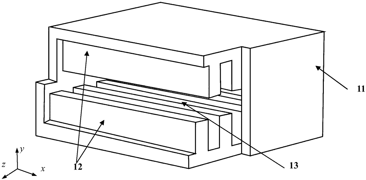
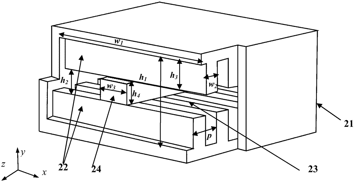
[0030] In this implementation manner, an example is taken of a staggered grating slow-wave structure loaded with a single rectangular metal pillar with a working frequency range of 0.35-1.55 THz. Such as figure 2 As shown, it includes a rectangular parallelepiped housing 21, the lower bottom surface and the upper top surface of the housing 21 have rectangular grid teeth 22 arranged periodically along the axial direction, and a belt-shaped electron injection channel formed between the upper and lower rectangular grid teeth. 23, also includes rectangular metal posts 24 loaded in the upper and lower rectangular grid teeth 22.

[0031] The number of rectangular metal pillars is 1, and the number of electron injection channels is 2. Such as figure 2 As shown, the specific dimensions are set as follows: the width and height of the cross-section of the slow wave structure are respectively w 1 = 320 μm and h 1 = 160μm, the period is p = 60μm, the height of the electron beam chan...

Embodiment 2

[0033] In this implementation manner, an example is taken of a slow-wave structure of an interlaced grid loaded with double rectangular metal pillars with a working frequency range of 0.35-1.87 THz. Such as Figure 5As shown, it includes a rectangular parallelepiped shell 51, the lower bottom surface and the upper top surface of the shell 51 have rectangular grid teeth 52 arranged periodically along the axial direction, and strip-shaped electron injection channels formed between the upper and lower rectangular grid teeth. 53 , further comprising a first rectangular metal column 54 and a second rectangular metal column 55 loaded in the upper and lower rectangular grid teeth 52 .

[0034] The number of rectangular metal pillars is 2, and the number of electron injection channels is 3. Such as Figure 5 As shown, the specific dimensions are set as follows: the width and height of the cross-section of the slow wave structure are respectively w 1 = 320 μm and h 1 = 160μm, the p...


PUM


Abstract

The invention discloses a staggered grid slow wave structure loaded by rectangular metal columns, which adopts a rectangular solid shell, rectangular grid teeth distributed along a longitudinal direction periodically on an upper top surface and a lower bottom surface of the shell, one or more rectangular metal columns loaded in the middle of the grid teeth and a structure composed of two band-shaped injection channels. The high-order mode operation of slow-wave structure can be realized by using the rectangular metal columns. This staggered grid slow-wave structure can effectively suppress thelow-order mode sum and work in the high-frequency band with the same structure size. The millimeter-wave terahertz traveling wave tube / backward wave tube based on this slow-wave structure has many advantages, such as compact structure, high electronic efficiency, high output power and so on. The structure has a wide application prospect in high data rate communication systems, high precision imaging systems, radar complete appliance systems and so on.

Description

[technical field] [0001] The invention belongs to the technical field of microwave vacuum electronics, and in particular relates to an interlaced grating slow-wave structure loaded with rectangular metal pillars for millimeter-wave / terahertz wave-shaped injection traveling-wave tubes / back-wave tubes. [Background technique] [0002] Terahertz technology is one of the most promising technologies today, and it has broad application prospects in many fields such as high data rate communication, security inspection imaging, high-precision radar, biomedicine and material detection. Although terahertz technology has made important research progress, terahertz technology is still in the exploratory stage, and there are still few real applications. One of the most important reasons is the lack of high-power terahertz sources. Vacuum electronic devices are an important technical means for realizing high-power terahertz sources. Traveling wave tube / return wave tube is the most import...

Claims


Application Information

Patent Timeline
Patent Type & Authority Applications(China)
IPC IPC(8): H01J23/28
Inventor 舒国响钱正芳周灿钦孙一翎范姝婷陈乐戴翔宇熊浩梁豪
Owner SHENZHEN UNIV
Why Eureka
Try Eureka