Heat dissipation structure

A technology of heat dissipation structure and heat sink, applied in cooling/ventilation/heating transformation, modification by conduction heat transfer, transformer/inductor cooling, etc. The efficiency, service life and reliability of power components

Active Publication Date: 2018-12-11
ZTE CORP
View PDF5 Cites 7 Cited by
  • Summary
  • Abstract
  • Description
  • Claims
  • Application Information

AI Technical Summary

Problems solved by technology

[0003] In electronic equipment, the circuit board integrates more and more devices such as data processing main chips and optical modules with increasing power consumption. These devices not only occupy a large amount of layout area in the length and width direction of the circuit board , for the high direction, the device also needs to have a thick heat sink on its back to achieve heat dissipation. In this way, the height of the device with the hea

Method used


Image

  • Heat dissipation structure
  • Heat dissipation structure
  • Heat dissipation structure

Examples


Embodiment 1

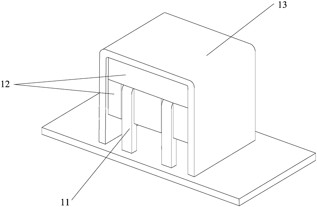
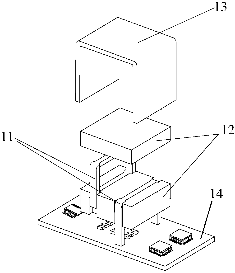
[0096] refer to image 3 , Figure 4 ,in, image 3 An exploded view of the inductor with an integral heat sink, Figure 4 It is an assembly diagram of an inductance with an integral heat sink, and the inductance, as the first type of heating component, includes: winding 11 and magnetic core 12; among them,

[0097] The magnetic core 12 is divided into two parts, the first part of the magnetic core 12 is adjacent to the heat sink 13, and the second part of the magnetic core 12 is adjacent to the circuit board. The second magnetic core 12 is divided into three sub-blocks, with windings 11 arranged between two sub-blocks, and two windings 11 arranged between the three sub-blocks.

[0098] The inductor is supported on the circuit board 14 through the winding 11 and has an overhead structure relative to the circuit board 14 .

[0099] The gap between the magnetic core 12 and the winding 11 of the inductor is filled with a flexible heat-conducting material. A flexible thermally...

Embodiment 2

[0103]refer to Figure 5 , Figure 6 ,in, Figure 5 An exploded view of the inductor with an integral toothed heat sink, Figure 6 It is an assembly diagram of an inductance with an integral toothed heat sink, and the inductance as a magnetic device includes: winding 11, magnetic core 12; wherein,

[0104] The magnetic core 12 is divided into two parts, the first part of the magnetic core 12 is adjacent to the heat sink 13, and the second part of the magnetic core 12 is adjacent to the circuit board. The second magnetic core 12 is divided into three sub-blocks, with windings 11 arranged between two sub-blocks, and two windings 11 arranged between the three sub-blocks.

[0105] The inductor is supported on the circuit board 14 through the winding 11 and has an overhead structure relative to the circuit board 14 .

[0106] The gap between the magnetic core 12 and the winding 11 of the inductor is filled with a flexible heat-conducting material. A flexible thermally conducti...

Embodiment 3

[0110] refer to Figure 7 , Figure 8 ,in, Figure 7 An exploded view of the inductor with two discrete toothed heat sinks, Figure 8 It is an assembly drawing of an inductor with two discrete toothed heat sinks, and the inductor as a magnetic device includes: a winding 11 and a magnetic core 12; wherein,

[0111] The magnetic core 12 is divided into two parts, the first part of the magnetic core 12 is adjacent to the heat sink 13, and the second part of the magnetic core 12 is adjacent to the circuit board. The second magnetic core 12 is divided into three sub-blocks, with windings 11 arranged between two sub-blocks, and two windings 11 arranged between the three sub-blocks.

[0112] The inductor is supported on the circuit board 14 through the winding 11 and has an overhead structure relative to the circuit board 14 .

[0113] The gap between the magnetic core 12 and the winding 11 of the inductor is filled with a flexible heat-conducting material. A flexible thermally ...


PUM

PropertyMeasurementUnit
Thermal conductivityaaaaaaaaaa

Abstract

The invention discloses a heat dissipation structure. The heat dissipation structure comprises a heat dissipation device, a first type heat generating assembly and a second type heat generating group.The first type heating component comprises a winding and a magnetic core. The second type heating component comprises a heating device. The heat dissipation device comprises a heat dissipation fin and a circuit board with a heat conduction channel. Wherein the winding is arranged between the magnetic core and the magnetic core, and the first type heating component is supported on the circuit board by the winding and has an overhead structure with respect to the circuit board; The heat dissipation fin cover is arranged on the outer surface of the first type heating component, and is integrallystructured with the first type heating component, wherein, the height of the integrally structured fin cover is greater than or equal to a preset value; The bottom of the heating device is provided with a first pad, and the first pad is arranged on the circuit board. Heat sink is soldered on the circuit board through one or more soldering terminals; The heat of the heating device is transferred to the circuit board through the first pad and to the heat sink through the heat conduction channel on the circuit board.

Description

technical field [0001] The invention relates to heat dissipation technology of electronic devices, in particular to a heat dissipation structure. Background technique [0002] With the continuous increase in power and volume reduction of electronic equipment, the application space of each device in electronic equipment becomes more and more compact. High assembly density and high power density have become two important directions for the development of electronic equipment. [0003] In electronic equipment, the circuit board integrates more and more devices such as data processing main chips and optical modules with increasing power consumption. These devices not only occupy a large amount of layout area in the length and width direction of the circuit board , for the high direction, the device also needs to have a thick heat sink on its back to achieve heat dissipation. In this way, the height of the device with the heat sink can reach more than ten millimeters to tens of ...

Claims


Application Information

Patent Timeline
IPC IPC(8): H05K7/20
CPCH05K7/2039H01F27/08H01F27/22
Inventor 张里根陈丽霞张滨
Owner ZTE CORP
Why Eureka
Try Eureka