Pulse current assisted hollow shunt billet micro-forming die and method

A pulsed current, micro-forming technology, applied in the direction of metal extrusion dies, etc., can solve the problems of slow heating speed, low die life, and difficulty in filling small die cavities.

Active Publication Date: 2018-12-14
HARBIN INST OF TECH
View PDF8 Cites 7 Cited by
  • Summary
  • Abstract
  • Description
  • Claims
  • Application Information

AI Technical Summary

Problems solved by technology

[0003] The invention provides a pulse current assisted blank hollow shunt micro-forming mold and method to solve the bottleneck problems of slow heating of the blank of the micro-parts of hard-to-deform materials such as titanium alloy, difficulty in filling the cavity of the micro-mold, and low mold life.

Method used


Image

  • Pulse current assisted hollow shunt billet micro-forming die and method
  • Pulse current assisted hollow shunt billet micro-forming die and method
  • Pulse current assisted hollow shunt billet micro-forming die and method

Examples


specific Embodiment approach 1

[0024] Specific implementation mode one: combine figure 1 and Figure 4 Explain, a pulse current assisted blank hollow shunt micro-forming mold, which includes a mold handle 1, an upper plate 2, a punch fixing plate 5, a punch 6, a die 8, and a die fixing block 9 arranged in sequence from top to bottom , demoulding pad 10 and lower plate 11; the punch 6 is fixed in the upper, lower and smaller step through holes on the punch fixing plate 5, the die handle 1 and the punch fixing plate 5 are respectively connected with the upper plate 2, and the concave The mold fixing block 9 is connected with the lower plate 11, the upper end of the die fixing block 9 is grooved and embedded with the die 8, and the lower end is opened with a passage through the cavity of the die 8, and the demoulding pad 10 is arranged in the passage, with The blank 14 of the split hole is arranged in the cavity of the die 8, and the lower end is in contact with the demoulding pad 10, the cavity is matched wi...

specific Embodiment approach 2

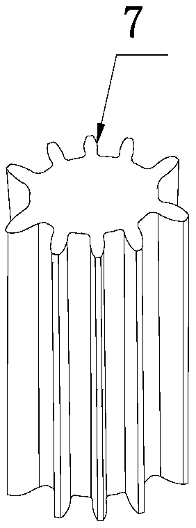
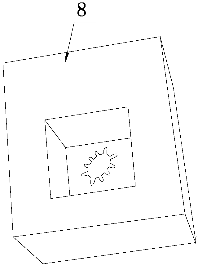
[0026] Specific implementation mode two: combination figure 2 and image 3 Explanation, the shape of the male mold 7 in this embodiment is the same as the contour shape of the micro-component, and the cavity of the die 8 is the same as the contour shape of the micro-component.

specific Embodiment approach 3

[0027] Specific embodiment three: the punch 7 has a micro-part outer contour structure, the cavity inner contour of the die 8 is a micro-part structure, and the die 8 is processed with a punch guide groove 8- which communicates with the inner cavity. 1. The matching gap between the punch 6 and the punch guide groove 8-1 is less than 5 μm, and the matching gap between the cavity of the die 8 and the punch 7 is less than 10 μm. Other compositions and connections are the same as in the first embodiment.

[0028] In the above two embodiments, the punch 7 is independent from the overall structure of the mold, which reduces the processing difficulty of the punch 7 and facilitates assembly and replacement. The matching gap between the concave die 8 and the male die 7 of this embodiment is less than 10 μm, so that the forming accuracy of the formed micro parts (such as micro gears) is completely guaranteed by the concave-convex fit, which greatly reduces the dependence on the mold ass...


PUM

PropertyMeasurementUnit
heightaaaaaaaaaa
diameteraaaaaaaaaa
diameteraaaaaaaaaa

Abstract

The invention discloses a pulse current assisted hollow shunt billet micro-forming die and method and relates to a micro-forming die and method for miniature parts. In order to solve bottleneck problems that billets of miniature parts made of titanium alloy and other difficult-to-form materials have slow heating speeds, the micro die cavity is difficult to fill, the service life of the die is lowand the like, the micro-forming die comprises a die handle, an upper plate, a punch fixing plate, a punch, a female die, a female die fixing block, a demolding cushion block and a lower plate arrangedfrom top to bottom in sequence, wherein the punch is fixed in a stepped through hole which is large in top and small in bottom on the punch fixing plate. The forming method comprises the following steps: 1, die assembling, arranging the billet in the cavity of the female die, enabling pressure equipment to move downwards to drive the punch to move downwards so as to be in contact with the upper end face of the male die, continuously enabling the male die to move downwards to reach a certain pre-tightening pressure with the billet and stopping; 2, starting a pulsed power supply, heating the billets, and performing extrusion forming; 3, taking out the male die and the formed miniature parts. The invention belongs to the technical field of machine manufacturing and plastic micro-forming.

Description

technical field [0001] The invention relates to a micro-forming mold and method, in particular to a pulse-current assisted blank hollow shunting micro-forming mold and method, belonging to the technical fields of mechanical manufacturing and plastic micro-forming. Background technique [0002] In recent years, with the continuous expansion of the scale range of plastic micro-forming technology, the demand for material types has increased, and the application fields have continued to expand. The micro-forming process has shown stronger scale and material dependence. Due to the existence of the scale effect, the micro-forming performance and scale limit of the material are reduced, and the dimensional accuracy and consistency of the micro-formed parts are deteriorated. Especially for some difficult-to-deform materials, it is difficult to carry out the micro-forming technology solely relying on the load applied by the mold. For example, titanium alloy micro-gears, which are wid...

Claims


Application Information

Patent Timeline
Patent Type & Authority Applications(China)
IPC IPC(8): B21C23/14B21C29/00B21C25/02
Inventor 徐杰郭斌单德彬包建兴汪鑫伟王春举陈万吉
Owner HARBIN INST OF TECH
Why Eureka
Try Eureka