
A high power output fiber coupling device

A technology of output optical fiber and coupling device, which is applied in the application field of optical passive components, can solve the problems of troublesome adjustment, difficult disassembly and replacement of parts, and long time consumption, so as to achieve the effect of convenient operation and improved work efficiency

Active Publication Date: 2020-09-15
SHENZHEN PENGDA OPTOELECTRONICS TECH
View PDF4 Cites 0 Cited by
  • Summary
  • Abstract
  • Description
  • Claims
  • Application Information

AI Technical Summary

Problems solved by technology

[0005] In order to make up for the deficiencies of the existing technology and solve the problems of long time-consuming adjustment troubles, unsolvable heat dissipation and difficult disassembly and replacement of parts, the present invention provides a technical solution to solve this problem

Method used


Image

  • A high power output fiber coupling device
  • A high power output fiber coupling device
  • A high power output fiber coupling device

Examples


Embodiment approach

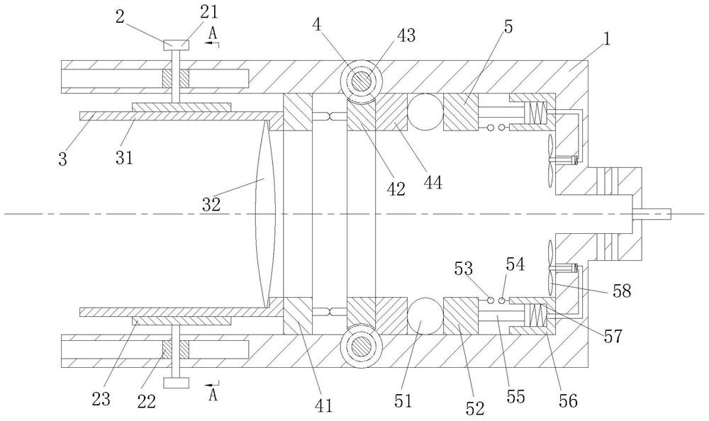
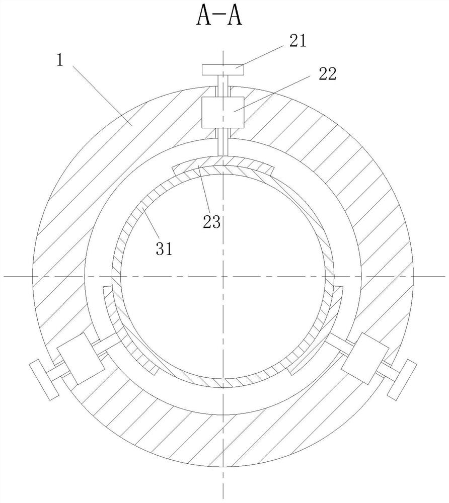
[0023] As an embodiment of the present invention, the radial adjustment mechanism 2 includes an adjustment knob 21, a slider 22 and a contact plate 23; the adjustment knob 21 is divided into two parts: a knob and a rotating shaft, and the rotating shaft is provided with threads. The adjustment knob 21 passes through the housing 1 and the slider 22, and is fixedly connected with the contact plate 23, and adjusts the position of the contact plate 23 through the adjustment knob 21, thereby adjusting the lens device 3; the slider 22 is a cuboid with a The threaded hole cooperates with the adjustment knob 21, and the slider 22 is installed in the rectangular groove on the housing 1, and can move in the rectangular groove, in order to facilitate the device to disassemble and replace parts; The plate 23 is arc-shaped, in order to increase the contact area with the lens device 3 and prevent the lens device 3 from being damaged due to excessive pressure due to the small contact area dur...


PUM


Abstract

The present invention relates to the application field of optical passive components, in particular to a high-power output optical fiber coupling device. During operation, the laser light enters from the left side and passes through the converging point of the lens and exits from the middle hole on the right side; The interaction of the three adjustment knobs fine-tunes the lens device, thereby adjusting the focus to the best position, contacting the end face of the optical fiber, adjusting the axial adjustment mechanism, rotating the worm, driving the rotation of the worm gear ring, and driving the wedge on the worm gear ring Move with the wedge on the moving ring to adjust the axial direction of the lens device and achieve the best focusing effect; at the same time, the laser will generate heat, and through the heat dissipation mechanism, the extrusion of the airbag and the rotation of the fan will be completed to accelerate the cooling Heat dissipation. The invention has the advantages of simple operation, high adjustment efficiency, convenient disassembly and replacement of components, self-radiation and cooling, and maximum self-protection of the device.

Description

technical field [0001] The invention relates to the application field of optical passive components, in particular to a high-power output fiber coupling device. Background technique [0002] In the late 1980s, with the maturity of optical fiber manufacturing technology and the development of solid-state lasers, fiber lasers began to become the focus of attention, and with the maturity of double-clad fiber and cladding pumping technology, high Power fiber lasers began to make breakthrough progress. Due to the advantages of fiber lasers such as small size, good compactness, convenient thermal management, and good beam quality, in recent years, high-power fiber lasers with fiber output have been used in optical communications, material processing, medical diagnosis and treatment, information storage, laser printing, laser It has been widely used in the fields of measurement and control, laser spectroscopy and nonlinear frequency conversion. [0003] There are also some techni...

Claims


Application Information

Patent Timeline
Patent Type & Authority Patents(China)
IPC IPC(8): G02B6/42G02B7/04
CPCG02B7/04G02B6/4206G02B6/4268
Inventor 钱福琦舒雄许源方福林李涵
Owner SHENZHEN PENGDA OPTOELECTRONICS TECH
Learn More